


Introduction to Arduino Pro Micro


Introduction to Arduino Pro Micro
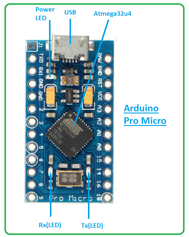
- Introduced by Sparkfun, Arduino Pro Micro is an Arduino compatible microcontroller board based on ATmega32u4.
- This board operates at the frequency of 16 MHz which is required for the synchronization of the internal functions.
- It comes with a built-in micro USB port that helps you test and program the Arduino board with a computer.
- Though this tiny beast is small in size, it can perform functions like regular Arduino boards. This board comes with a flash memory of 32KB. And SRAM and EEPROM memories are 1KB and 2.5KB respectively.
- The flash memory is the memory where the Arduino Program (sketch) is stored. While EEPROM memory is used to store long-term information and SRAM memory is used to produce and manipulate variables when it starts running.
- In addition, this board is compatible with breadboards which makes it an ideal pick for a range of testing projects before you actually incorporate this device into your electrical project.
- This board supports UART serial communication with two pins Rx and Tx. The former is the receive data line used to receive serial data while the latter is the transmission line used to transmit serial data.
- The board incorporates resettable poly-fuse mainly employed to secure the USB port. It keeps the board from consuming too much power from the computer. When the current exceeds the given limit, the resistance of this polymeric material increases while it heats up. When the overcurrent is removed from the device, this fuse cools down and its resistance comes back to its original value.
Arduino Pro Micro Datasheet
Before you install this board into your electrical project, it’s wise to go through the datasheet of the board that contains the main characteristics of the board. Click the link below to download the datasheet of Arduino Pro Micro.Arduino Pro Micro Features
The following are the main features of the Arduino Pro Micro board. CPU = 8bit Microcontroller = Atmega32u4 Digital I/O pins = 12 Oscillator = 16MHz USB = 1 ADC = 4x 10-bit ADC inputs PWM pins = 5 UART = 1 Reset button = no ICSP header = no Pin 13 LED = no Software Used = Arduino IDE Flash memory = 32KB EEPROM = 1KB SRAM = 2.5KB Size = 34mm x 18mmArduino Pro Micro Pinout
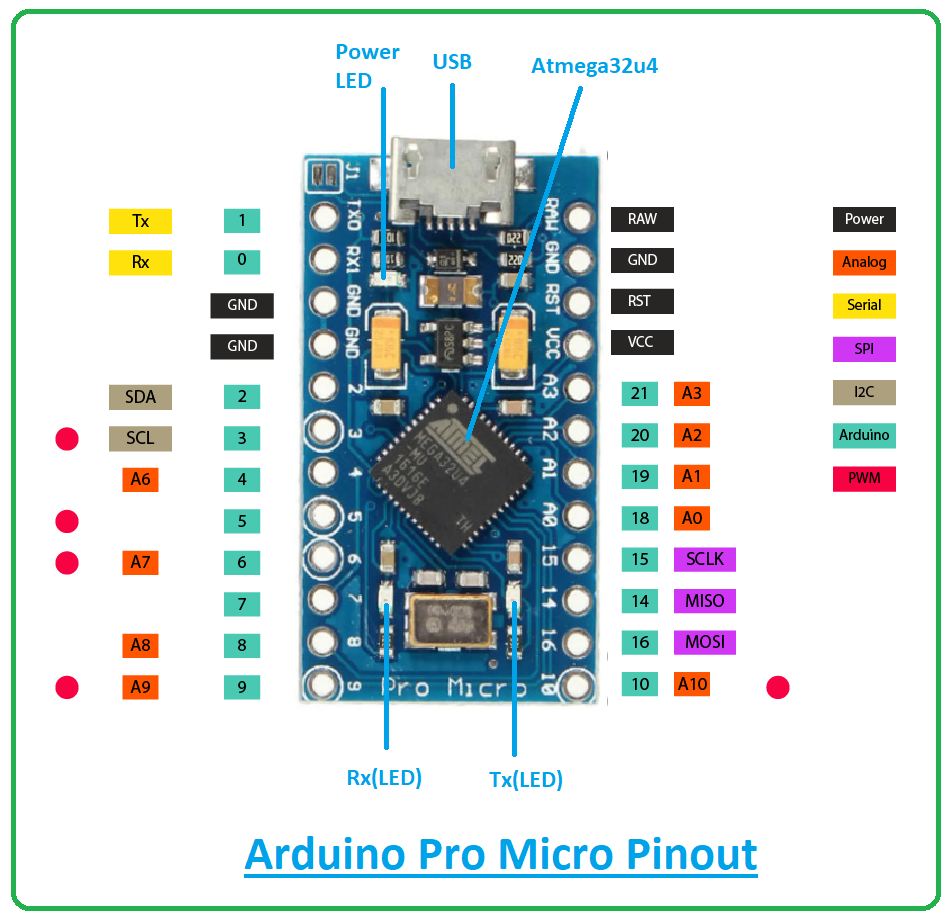
The following figure shows the pinout diagram of Arduino Pro Micro.
Arduino Pro Micro Pin Description
Hope you’ve got the sneak peek of this Arduino board. In this section, we’ll detail the pin description of pins incorporated on the board.Digital I/O Pins
There are 12 digital I/O pins available on the board that are either used as input or output based on the requirement. These pins are either OFF or ON. When they are ON they receive 5V and are considered as HIGH and when they are OFF they receive 0V and are considered LOW.Analog Pins
This board incorporates 9 channels of 10-bit ADC. These are analog pins that receive any number of values in contrast to digital pins that get only two values i.e. HIGH and LOW.PWM Pins
The Pro Micro board features 5 PWM channels which are used to get some of the analog output’s functions. When the PWM pins are triggered, the board creates analog results with digital means.UART Pins
Moreover, it supports UART serial communication with two pins Rx and Tx. Both pins are used to transmit and receive serial data.SPI Pins
This board comes with a serial peripheral interface (SPI) used to layout communication between the microcontroller and other peripheral devices such as and sensors shift registers.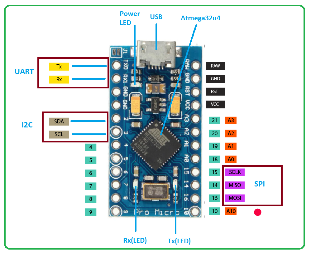
I2C Pins
- Two pins are used for I2C communication which is a two-wire communication protocol. One is SDA and the other is SCL.
- The former is a serial data line used to carry the data and the latter is a serial clock line used for the synchronization of all data transfer over the I2C bus.
Programming
- The Arduino IDE (integrated development environment) software is used to program this Arduino board. This software is introduced by Arduino.cc which is used to program all kinds of Arduino boards.
- This software is easy to use. As you install the software, you are given some basic LED blinking programs through which you can easily test the board on the go.
- This tiny little beast contains a built-in Bootloader that is used to burn the program and it sets you free from the drill of compiling and burning the program from the external burner.
- With a micro USB port, you don’t require a secondary processor as it appears to an attached computer as a keyboard and mouse. With this port, you can test and program the Arduino board directly from the computer.
Difference between Arduino Pro Micro and Arduino Micro
- Through both boards incorporate Atmega32u4 microcontroller they differ in few features.
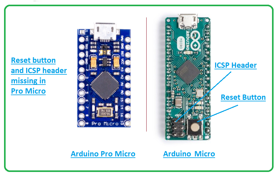
- The Micro board comes with a reset button and ICSP header while the Pro micro board doesn’t incorporate those features.
- Moreover, pro micro is smaller than micro board thus fewer pins are brought out to the Arduino terminal pins.
- The missing pins include AREF, A4, A5, SS, 11, 12, and 13. This also projects that pin 13 doesn’t carry LED but it still supports Tx and Rx pins with LEDs for serial communication.
- In addition, you cannot use the SPI interface in slave mode in the case of the Pro micro board as this board doesn’t bring out SS pin. And since the pro micro board cannot bring out AREF, the external ADC reference voltage ability is absent.
- It is important to note that, though the board doesn’t carry ICSP connector, still it supports ICSP interface through which you can program the board.
Arduino Pro Micro Applications
The ability to easily groove in hard to reach places makes this board an ideal pick for a range of applications. This board can be used in the following projects.- Windows PC lock/unlock application
- USB Trackpad
- USB Joystick
- Water Level Meter
- Electric Bike
- Creating a wireless keyboard
- Automatic Pill Dispenser

Hi i purchased a Diy kit for American truck simulator from Southern trucker gaming nd i have no clue how to program my pro micro for the high nd low range splitter and the high nd low range nd easy jake total of 9 wires
1 reply
Search 32 button control box from AMS studios. It has a complete build guide and code for setting up the matrix and buttons. I think it costs $5.00
Hi there, I came across this article trying to find information on how to use this micro-controller to do a fairly simple function, but since I am totally new to this type of thing I feel like I'm over my head. I have a project in mind to build a water induction system on my vehicle and need a way to take sensor readings (dc pulses...'frequency') from the MAF sensor (ranges a few thousand cycles per second...varies according to engine speed) and use these readings to sequentially fire solenoids to deliver water mist to the intake. Basically I need the controller to drive 2 or 3 transistors, in order at certain frequencies (dc pulses) and when the frequencies fall below threshold it will need to turn the transistors off (in sequence). Any help pointing me in the right direction in terms of learning basic coding for this would be immensely appreciated. Dante
Hello, I was wondering if you could direct me or tell me how I can wire the Arduino Pro Micro to a TB6612FNG to run 2 small DC motors. This stems from a Mod to Logitech G29 Pedals. They have added 2 Rumble/Vibration motors from an XBox Controller to simulate the feel of the car on your feet. It canbe seen in this vid, https://www.youtube.com/watch?v=8aLqqcEaUVk. I had asked if the Leonardo would operate these 2 motors directly as I'm under the impression that these wouldn't draw that much pwr seeing that the controllers are battery powered. It was suggested that I use the TB6612FNG for the motors with the Pro Micro. It didn't make sense to use a Leonardo and motor shield to run these 2 small motors. Any insite in this would greatly be appreciated, THANKS so very much!!
Comments
4