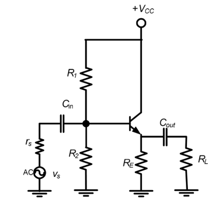
- Introduction of Common Collector BJT Amplifier.
- Basic Concepts for the Common Collector BJT Amplifiers.
- Implementation of Common Collector BJT Amplifiers in Proteus ISIS.
- Characteristics and advantages of Common Collector BJT Amplifiers.
Introduction
1st of all, We'll have a brief definition of the Common Collector Amplifier: " A type of Bipolar Junction Transistor Amplifier is called Common Collector BJT Amplifiers in which Collector is common to both Base, Base region is used for input and emitter is used to take the output of the Amplifier." It is one of the Configuration of the Transistor and is used in many kinds of circuits due to its efficiency. Other two Configurations are;- Common Base BJT Amplifiers.
- Common Emitter BJT Amplifiers.
Basic Concepts:
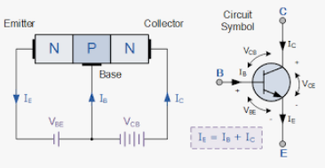
It is Always useful to get core information about the circuit before its Implementation. Let's see what a Common Collector amplifiers is. Type of transistor: Recall that the are two types of Transistors i.e, 1. NPN 2.PNP. the Transistor we are using NPN transistor for our Experiment because in this type, the electrons are majority carries that have more mobility than holes ( majority charge carriers in PNP transistors) therefore, we get quick and easy output due to best electron flow.
Current Gain = Emitter current/Base Current
? = IE/IB = ß + 1
Voltage Gain : Voltage Gain of Common Collector BJT Amplifier is considered to be the unity, i.e. 1 and is obtained by the formula given below: Voltage Gain=Vout/Vin where in Common Collector amplifier we give the input to Base and take the output from the emitter of the transistor. Emitter Current: in this Configuration the Emitter current is taken as the sum of base current and collector current. consequently, we say Ie=Ib+Ic we can use this equation in others ways as,Ib=Ie-Ic
Ic=Ie-Ib
we can also say that the collector current is approximately equal to Emitter current because base is very thin region and passes a minute amount of current through it.Implementation of Common Collector BJT Amplifier in Proteus ISIS
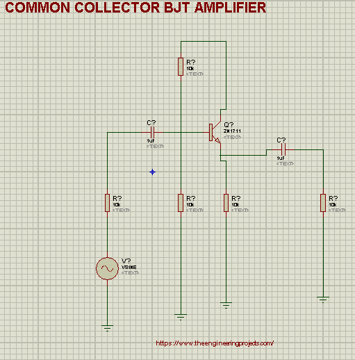
At the instance, we will test the circuit given in the circuit diagram in Proteus. the material for the Circuit is given below. Material Required:- Transistor (2N1711)
- Capacitor
- Resistor
- Vsine
- Oscilloscope
- Ground
- Take 1st four components from the "Pick device" library presented at the left corner of the screen.
- Set them at the working area according to the circuit diagram.
- Add the ground terminal by left clicking the screen >Go to Place>Terminal>Ground and add the ground Terminal.

- Add the DC source from "Generation Mode" to just above the circuit.
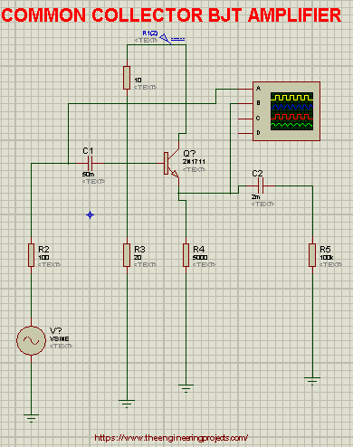
- Set the Oscilloscope just aside the circuit and Connect Channel A with input (Base) and the Channel B with the output ( Emitter).

- we will use the 120V for the DC Power source.
- One can clearly examine that the Values of the Components are given according to the table given below:
| Components | Values |
| Resistor R1 | 10ohm |
| Resistor R2 | 100ohm |
| Resistor R3 | 20ohm |
| Resistor R4 | 100kohm |
| VSine | Amplitude=220, Frequency=1000 |
| Capacitor 1 | 50m |
| Capacitor 2 | 2m |
| Oscilloscope | Channel 5V, Channel B=5V, Time=0.2mS-1 |
- After setting the values you can change the value of Oscilloscope to get the required output.
Characteristics
- The input Resistance of Common Collector Amplifiers is high.
- The power gain of this kind of amplifiers is medium.
- It has low output resistance.
- It has non-inverting effect (opposite to other two Configuration that gives the inversion of the wave).
- It has zero voltage gain.
Advantages of Common Collector BJT Amplifiers
- It is useful for the circuits where the high impedance is required.
- It is mostly used as voltage buffers as the voltage gain is unity.
- The Common Collector configuration is used in the Circuit where the engineers want the high current gain.
- Due to its high current gain, it is applied in circuits to drive heavy loads.
- We use it for voltage translation stage.


