
LM2575 Buck Converter Datasheet, Pinout, Features, Applications


Introduction to LM2575
- LM2575 is a voltage regulator and simplified version of switching power supplies that carry all functions required to step down the voltage in the circuit.
- This buck converter is incorporated with an integrated switch that can support load under 1A.
- LM2575 carries an excellent load line and load regulation. It comes in two versions: fixed output voltage version with voltage 3.3V, 5V, 12V, and adjustable output version that gives the ability to pick your desired output.
- It is also called the DC-to-DC power converter employed to step down the voltage from its input supply to its output load. The current increases during this voltage regulation.
- This regulator is integrated with a fixed-frequency oscillator of about 52 kHz and an in-built frequency compensation method.

- Frequency compensation is applied to reduce vibration and oscillation in the circuit. It can be obtained using resistance-capacitance networks.
- Apart from the remarkable load and line regulation, this device comes with a manual shutdown option through an external ON/OFF pin.
- Less external components are needed for this buck converter since it works at a fixed frequency of 52 kHz.
LM2575 Features
- Fixed versions with 3.3-V, 5-V, 12-V, and adjustable output versions
- Adjustable output version with voltage range: 1.2-V to 37-V ±4% maximum over load and line conditions
- Available in two packages named TO-263 and TO-220 packages.
- Can drive load under 1A.
- Comes with low power standby mode, commonly less than 200 µA.
- Uses easily available standard inductors and is highly efficient.
- 4.75 to 40 V is the input voltage range.
- 23V to 37V is the output voltage range.
- 80% efficiency.
- Excellent load and line regulations.
- Fixed internal oscillator frequency of 52 kHz.
- TTL shutdown capability.
- Protection against overcurrent and thermal shutdown.
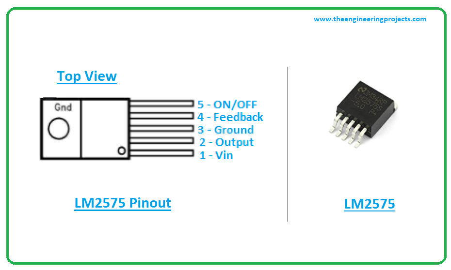
LM2575 Pinout
LM2575 comes with five terminals. The following figure shows the pinout diagram of LM2575.
LM2575 Datasheet
Before you install this component into your project, it’s wise to scan through the datasheet that covers the main characteristics of the component. Click the link below and download the datasheet of LM2575.LM2575 Applications
LM2575 is used in the following applications.- Used in a simple efficient step-down regulator.
- Used as a pre-regulator in linear regulator
- Used to drive load under 1A.
- Incorporated in On-card switching regulators.
- Employed in a positive-to-negative converter.
×
![]()


 1 user


 Continue Wishlist


 Getting Started Guide
 Help Center
 Contact us
 Doist Blog
 Privacy
 Security
 Terms of Service
 What's new: Channel Descriptions


 Electronic Components
 jameswilson
 0 Comments


 2.3k
2.3k
 953
953
 921
921
 2.1K
2.1K
 Introduction to lm2575
lm2575 pinout
lm2575 features
lm2575 applications

 Sunday, September 27, 2020


