Hello friends, I hope you all are doing great. In today’s tutorial, we will have a look at What is Bistable Multivibrator and how it can be used in different circuits. In this type of multivibrator, the circuitry can operate in any state according to a signal provided at its input while it does not happen in a monostable multivibrator. This arrangement is also defined as a flip flop because flip flop also operates at more than one condition. It also has the ability to store a single bit of information so it is mostly used in logic circuits and in computer data storage part.
This vibrator like other vibrators is used for the production of square waves with providing some delay. These circuits are constructed with numerous kinds of semiconductor components. The most used semiconductor device circuits are operational amplifiers. In today's post, we will have a look at its working, construction, applications and different parameters related to it. So let's get started with What is Bistable Multivibrator.
What is Bistable Multivibrator
- Bistable Multivibrator has 2 operating conditions so it is called bistable, it is also known as a 2-shot multivibrator.
- Due to working at two different modes it needs 2 input signal for shifting from one operating mode to others.
- When first input signal is provided it shifts its operation to second state when second signal provided it come back to previous state.
- Its another name is flip-flop multivibrator because like flip flops its changes its operation state and regain it after some interval.
- In the given figure, its structure is shown that consists of 2 NPN transistors that is denoted as Q1 and Q2.
- At both of these transistors collector 2 loads resistors, RL1 and RL2 are attached.
- The output terminal of the first transistor is connected with the input of the second transistor through resistor R1 and output of the second transistor is provided at input of first transistor through the resistor R2.
- Both of the resistance R1 and R2 are connected with a capacitor in parallel. The purpose of these two capacitors is to enhance the switching feature of circuitry so they are also known as commutating capacitors.

Bistable Multivibrator Working
- Now we discuss the working of this vibrator, for this, we discuss the circuitry that given below figure its construction and components we already discuss so now we the working of these components.
- When input power is provided to the input terminals of first transistor-transistor starts its operation due to a difference in its feature than the other transistor.
- When it first transistor starts its operation it goes into saturation state. Due to this value of voltage decreases at the collector terminals.
- As we know the collector of Q1 is connected with the base terminal of a second transistor due to this it goes into the cutt-off region.
- Then the voltage at the collector increases to Vcc, this increment in voltage causes to further saturate the first transistor as this voltage is connected with base of Q1 through the resistance R2.
- It is the first operating condition of bistable multivibrator in which first transistor Q1 is in working state while Q2 is off.
- This first condition continuous to that point we do not provide the negative signal to first transistor Q1 and positive polarity to transistor Q2.
- Now if we provide the positive polarity signal to the second transistor Q2 by the capacitor C2 connected with it.
- This Process will change the second transistor Q2 from saturation mode to cut-off mode, and voltage will decrease at a collector of Q2.
- As the collector of transistor Q2 is attached with the base of transistor Q1 with the decrement in the voltage at the collector of causes to decrease voltage at transistor Q1 base.
- This cause to the second transistor obtain saturation state and it is the second operation mode of this module in which the first transistor is off and second is in an operating state.

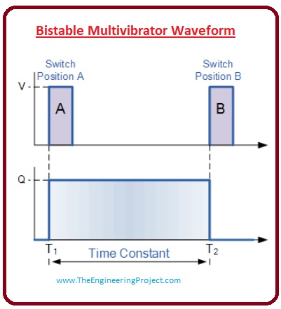
Bistable Multivibrator Waveform
- The output waveform generated by the has smaller wavelength or larger according to circuit requirement in rectangle shape.
- The first end of the rectangle waveform depends on the first input signal and vary according to it and second relies on the second input signal, the resultant waveform is drawn in a given figure.
- Switching variation among these 2 modes can create bistable circuitry but in some cases it is possible.

TTL Bistable Multivibrators
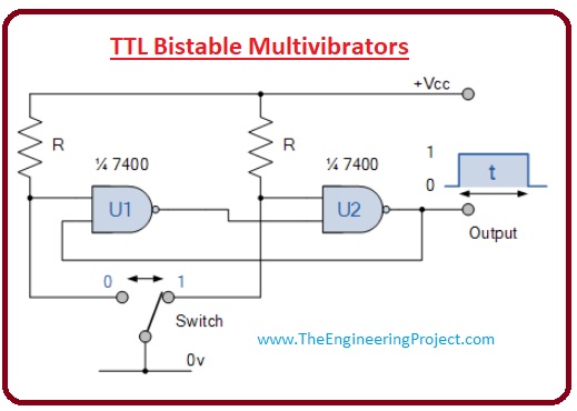
- As we above constructed this circuitry by using 2 different transistors now we use integrated circuits for the production this vibrator.
- The given circuitry explains the circuitry of a bistable vibrator having two NAND gates.
- This kind of circuits arrangments is known as the Bistable Flip-Flop, in this circuitry, there is a switch that is single pole through a switch (it is such switch that takes one input and can regulate 2 different output). This switch provides logic one and zero to this circuitry.

Application of Bistable Multivibrator
- These are some applications of the bistable multivibrator.
- It used in different storage devices and for counting of binary numbers.
- For frequency division in different circuits.
- It used for the production of different clock pulses.
- It used for different relay controller.
- It used in the different circuit as a toggle switch.
That is complete post on bistable multivibrator I have mentioned each and everything related to this module in this tutorial.


