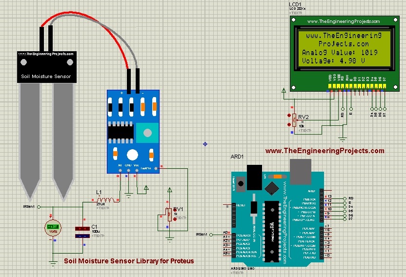

Soil moisture sensors are used to measure the water content in the soil. They use capacitance to measure the dielectric permittivity of the soil which defines the function of the water content. Before further ado, let’s dive in and have a look at How to download and simulate Soil Moisture Sensor Library for Proteus:
| Where To Buy? | ||||
|---|---|---|---|---|
| No. | Components | Distributor | Link To Buy | |
| 1 | LCD 20x4 | Amazon | Buy Now | |
| 2 | Arduino Uno | Amazon | Buy Now | |
Soil Moisture Sensor Library For Proteus
- You can download the Proteus Library zip file of Soil Moisture Sensor Library by clicking the button below.
- It’s a .zip file that contains two folders inside i.e. Proteus Library & Proteus Simulations.
- The real fun starts right here right away.
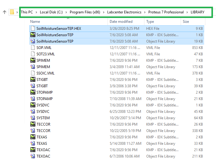
- Open proteus library folder that contains three files named:
- SoilMoistureSensorTEP.IDX
- SoilMoistureSensorTEP.LIB
- SoilMoistureSensorTEP.HEX
- Copy and paste these three files in the Library folder of your Proteus software:
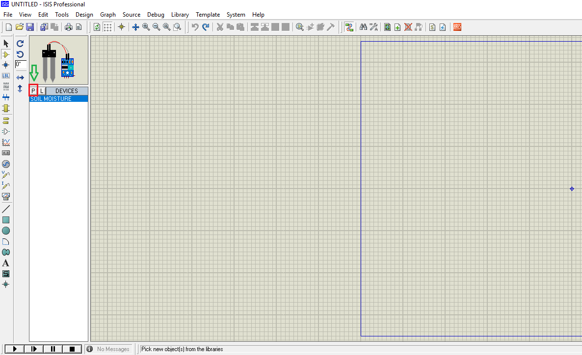
- Now, we need to run the Proteus ISIS software and don't forget to restart, if it's already open.
- Look for the Soil Moisture in the component’s search box as shown below.
- After installing the Library successfully, you’ll get similar results as below:
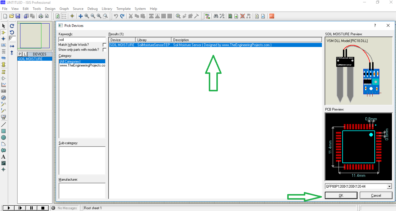
- You can see in the figure above we have one Soil Moisture Sensor.
- Now simply place this Soil Moisture Sensor in your Proteus workspace, as mentioned below:
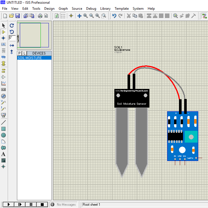
- You can see in the figure above, I have placed one Soil Moisture Sensor inside the Proteus workspace.
- This sensor carries 4 pins in total, named:
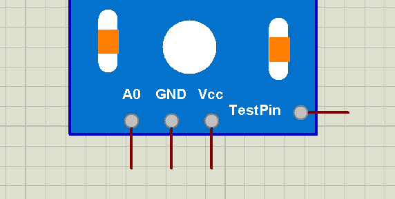
- V (Vcc): We’ll provide +5V here.
- G (GND): We’ll provide ground here.
- Ao (Out): It’s an analog output signal from the sensor.
- TestPin: It is used for simulation purposes only. Soil Moisture Sensor doesn’t contain this pin in real.
Adding Sensor’s Hex File
- After this drill, we’ll add the Sensor’s Hex File, which we have downloaded and placed in the Library folder.
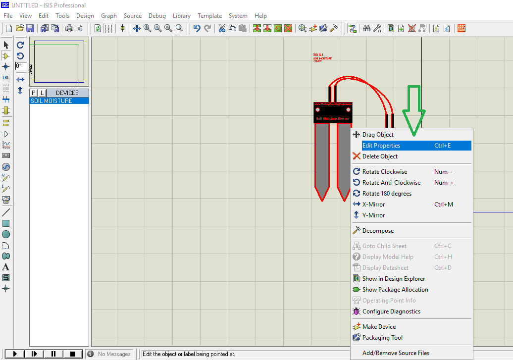
- To do that, right-click on your Soil Moisture Sensor and then click on “Edit Properties” as below:
- Or you can double click the Soil Moisture Sensor, it will pop the window below:
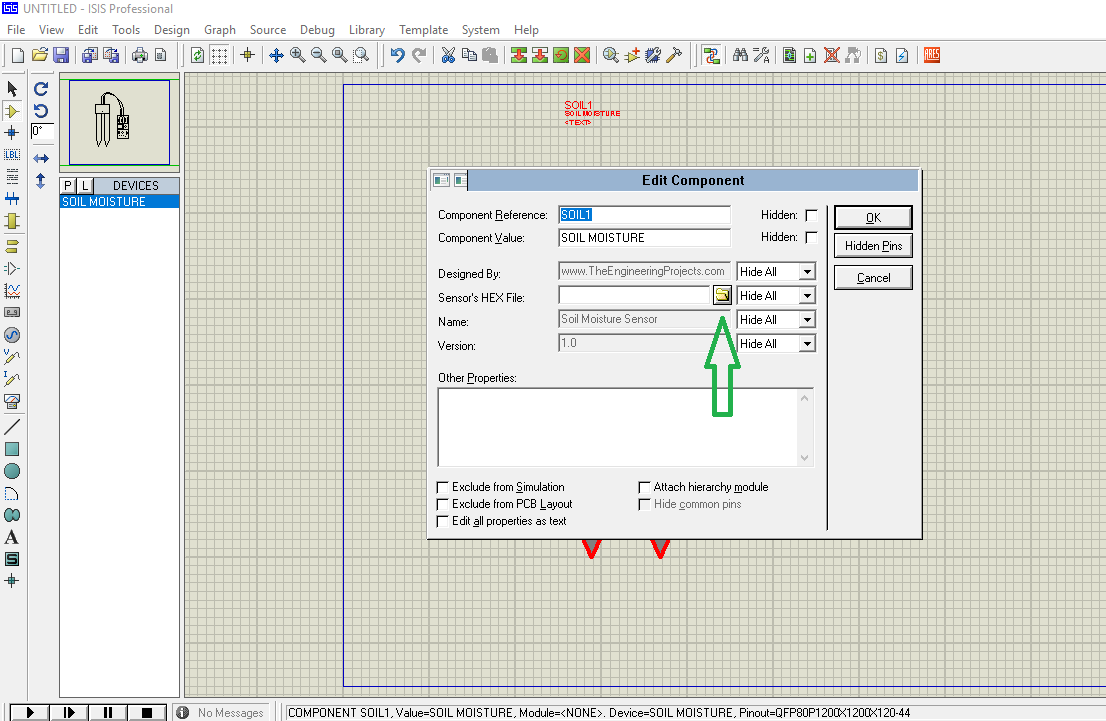
- Click on the Browse button and add SoilMoistureSensorTEP.HEX file available in the Proteus Library section as shown in the figure below:
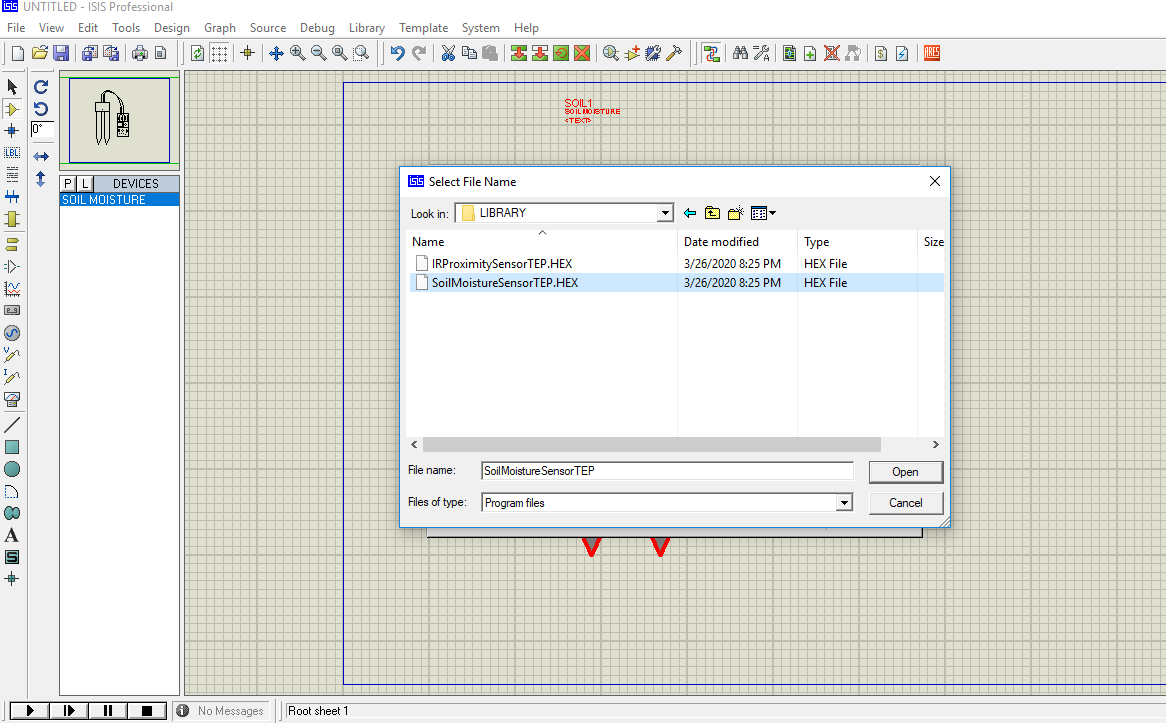
- After adding the Sensor’s Hex File, click on the ‘OK’ button to close the ‘Edit Properties’ Panel.
- Our Soil Moisture Sensor is now ready to simulate in our Proteus ISIS.
- We’ll design a small circuit to thoroughly understand the working of this Soil Moisture Sensor.
Proteus Simulation of Soil Moisture Sensor
- Here, I’m designing a simple circuit. I’ve attached a variable resistor with the Test Pin & added a Voltmeter at the Output pin, as shown in the figure below:
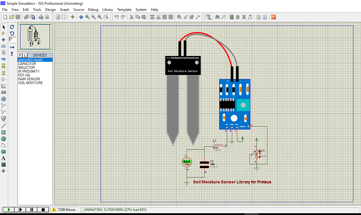
- This resister defines the soil water content in the proteus simulation.
- When the resistance is maximum at the test pin, the circuit shows zero volts across the voltmeter, which means the sensor is either in the dry ground or taken out of the ground i.e. giving zero moisture value of the water content.
- And when resistance is zero, the circuit will show the maximum voltage across the voltmeter which indicates the sensor is inserted in a wet ground i.e. water contents in the soil are too high.
- This is important. We have attached the output pin with an LC filter. This filter is not required in real hardware implementation.
- We are using it in Proteus Simulation only as Proteus gives the peak-to-peak value and we have to convert that PP value into Vrms.
- If you are working on a real sensor then you don’t need to add this LC circuit.
- Now, let’s run this Proteus Simulation and if you have done everything as mentioned, it will show the result mentioned in the figure above.
Simulation of Soil Moisture Sensor with Arduino
Now, let's interface this sensor with a microcontroller.- We have attached the output of the sensor appearing across the voltmeter with the A0 pin of the microcontroller as below.

You can see we get the analog value 1019 when the voltage across the voltmeter is 4.98V
This is it. I hope you find this tutorial helpful. This will help engineering students in simulating their semester projects in proteus. In the next tutorials, I’ll be sharing and adding more libraries of sensors. You’re most welcome to share your suggestions with the sensors you want me to libraries of. If you’re unsure or have any questions, you can ask me in the section below. I’ll help the best way I can. Thank you for reading this article.


