As it's our first tutorial, so today, we will have a look at a detailed Introduction to Control systems. Before starting with technical details, I would like to simplify things, by first providing the basic concept of a Control System. So, let's get started:
Introduction to Control Systems
- A system, whose output can be managed, controlled or regulated by varying its input is called Control System.
- If we look around, we will find many control systems in our surroundings i.e. Refrigerator, Air Conditions, Washing Machines etc.
- A control system can also be a combination of smaller control systems and is normally used to get desired/required output.
- Its block diagram is shown in the below figure:
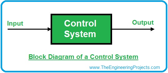
- The above figure represents a simple control system and we can think of this control system as a mathematical equation i.e.
X + 5 = Y
where, X is input, Y is output and Constant 5 is acting as a Control System.
- So, by changing the value of the input parameter ( X ), we can change our output value (Y).
- Similarly, if we want a particular output value, we can achieve it by fixing the input value.
Real Life Example of a Control System
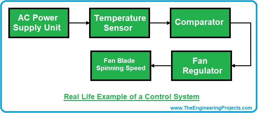
As I have mentioned earlier, we are literally surrounded by control systems, these days. Keeping this simple, let's have a look at the example of a smart fan, which regulates its spinning speed with respect to atmospheric temperature.
- A pre-installed Temperature sensor reads the temperature, which is then fed into Comparator.
- The comparator compares current temperature with user-inputted temperature value and then regulates the Fan speed.
Hence the input parameter i.e. temperature helped us in changing the system's output i.e. Spinning Speed. Below is the block diagram for representing the control system of a smart fan:
Now I hope that you can quite easily find different control systems in your surroundings. Now let's have a look at Main two Types of Control Systems:
Types of Control Systems
Control Systems are classified into two main categories, which are:
- Open Loop.
- Closed Loop.
Let's discuss them one by one, in detail:
Open Loop Control System
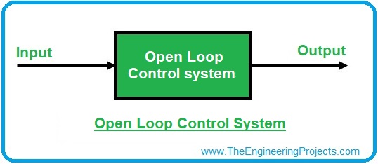
- In Open Loop Control Systems, we have three main components i.e. Input, Controller & Output.
- Input signal is directly fed to the controller, which utilizes it and generates the required output.
- In Open Loop systems, generated output has no affect on the Input signal i.e. no feedback provided.
Example
Here we will be discussing two examples of open loop control systems, to get a better understanding of the process.
Clothes Dryer is a very simple example of an open loop system. When damp clothes are put in the dryer machine, the operator/user sets the time for drying the clothes. This time acts as the input signal for the dryer. Correspondingly at the end of that time, the machine stops and clothes can be taken out. Now the thing to be noted here is that no matter if the clothes are dry enough or not, the machine will stop because of the time (input signal) fed to it. So the output of the system does not affect the input in this case. For a better understanding the block diagram of a cloth dryer control system is shown below:

Traffic Light system is another easy-to-understand example of an open loop system. Certain input signals are fed to the controller, which then displays one of the three lights at the output turn by turn. The direct input signals can be altered to change the output light but the output has no affect on the input. As we are not passing any feedback i.e. which light turned ON or OFF.
Closed Loop Control System
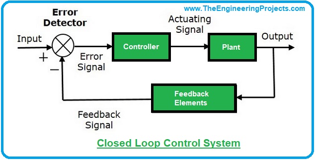
- Closed Loop Control System (Feedback control system) is an advanced automated system, which generates the desired output by using inputs, Controllers and feedback elements.
- These systems use feedback elements to fed the Output back to the controller. By doing that, we can compare the current output with input to get errors.
- Here's the block diagram of a Closed Loop Control System:

The block diagram above is an excellent representation of a closed loop control system. As seen, the system output is being fed back to the controller through an error detector. The function of the error detector is to find the difference in the input and output signal, and feed this difference to the controller so that the output can be adjusted. In this way, the system output is being automatically adjusted all the time with the help of the feedback signal and the operator does not have to worry about it.
Example
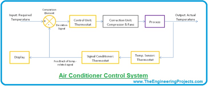
The air conditioner is a very typical example of a closed loop control system. The input signal in the form of required room temperature is fed into the controller of the air conditioner. The compressor along with its various electrical and mechanical components helps in achieving the required temperature. Now, whenever the room temperature changes, the temperature sensor at the output senses the change in the room temperature and the signal from the sensor is calculated by the error detector and fed back to the controller through the feedback loop to maintain the required room temperature. In this way, the required output is always maintained automatically without any manual interference. The block diagram illustration of this process is shown below:
Pros and Cons of Open and Closed loop
- It must have been cleared by now that wherever an accurate and precise system is required, feedback closed-loop control system is the answer, as they provide the feedback and thus automatically reduces the error while open loop control systems are not reliable enough to provide an accurate output.
- However another thing to be kept in mind here is the cost of the system. More precision and complexity mean a greater cost. So closed-loop control systems are clearly more expensive than open loop control systems. Open loop control systems are cheaper and cost effective.
- Last but not the least, Open loop control systems are also simpler to design as compared to closed loop control systems.
SISO and MIMO Control Systems
Control systems are also classified into these two categories, named as:- SIngle Input Single Output systems. (SISO)
- Multiple Input Multiple Output systems. (MISO)
Examples of SISO and MIMO Control Systems:
A fan speed control is a very common example of a Single Input Single Output system. A single input in terms of voltage is supplied to the system which in turn results in the fan working. On the other hand, a Radio system is a typical example of a Multiple Inputs Multiple Outputs system. A combination of Input signals is applied and transmitted over multiple lines to produce the required communication signals at the output. So this was all about SISO and MIMO control systems. The concept is pretty much basic but the same statement cannot be true for their applications. They are very versatile and at the same time very much used around us in our daily lives. So being done with these for now, I think it's time to move on to another interesting classification of the control systems.Continuous and Discrete Time Control System
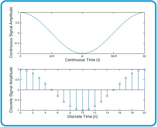
Before discussing the continuous and discrete time control system, it is important to understand the concept of a continuous time signal and a discrete time signal:- A continuous time signal refers to a signal, which is continuous in the time domain.
- On the other hand, when a signal is discrete in the time domain, i.e. it can be obtained at discrete time intervals, it is called a discrete time signal.
So now coming towards the continuous-time control system and a discrete-time control system:
- As we know the difference, the only thing needed to understand is that in a continuous time control system, all the signals (including the input & output signals) are continuous in time.
- Whereas in a discrete time control system, all the signals of the control system (including the input and output signals) are discrete time signals.
So guys, this was all about the basics of control systems today. This topic is very elaborate including the different types of controllers and their design and everything, but I have tried to keep it simple and introductory as per the topic's name. For an in depth study of control systems and their controller design, stay tuned with this control systems tutorial by email. In the next lecture, we will have a look at the detailed Introduction to Transfer Functions. For now, I'm hoping that this would prove helpful for your basic concept and understanding. Till next tutorial, take care & have fun !!! :)


