This diode is mostly used in radio frequency (RF) circuits or in power supplies. So let's get started with the basics of Schottky Diode:
Schottky Diode
- Schottky Diode (also called Schottky Barrier Diode or Hot Carrier Diodes), discovered by German physicist Walter H. Schottky, is a special type of diode in which the P-layer(of PN junction) is replaced by the metal layer(i.e. Aluminium, Tungsten, Molybdenum, Platinum, Chromium etc.), while the N layer is of silicon(semiconductor - same as in normal diode).
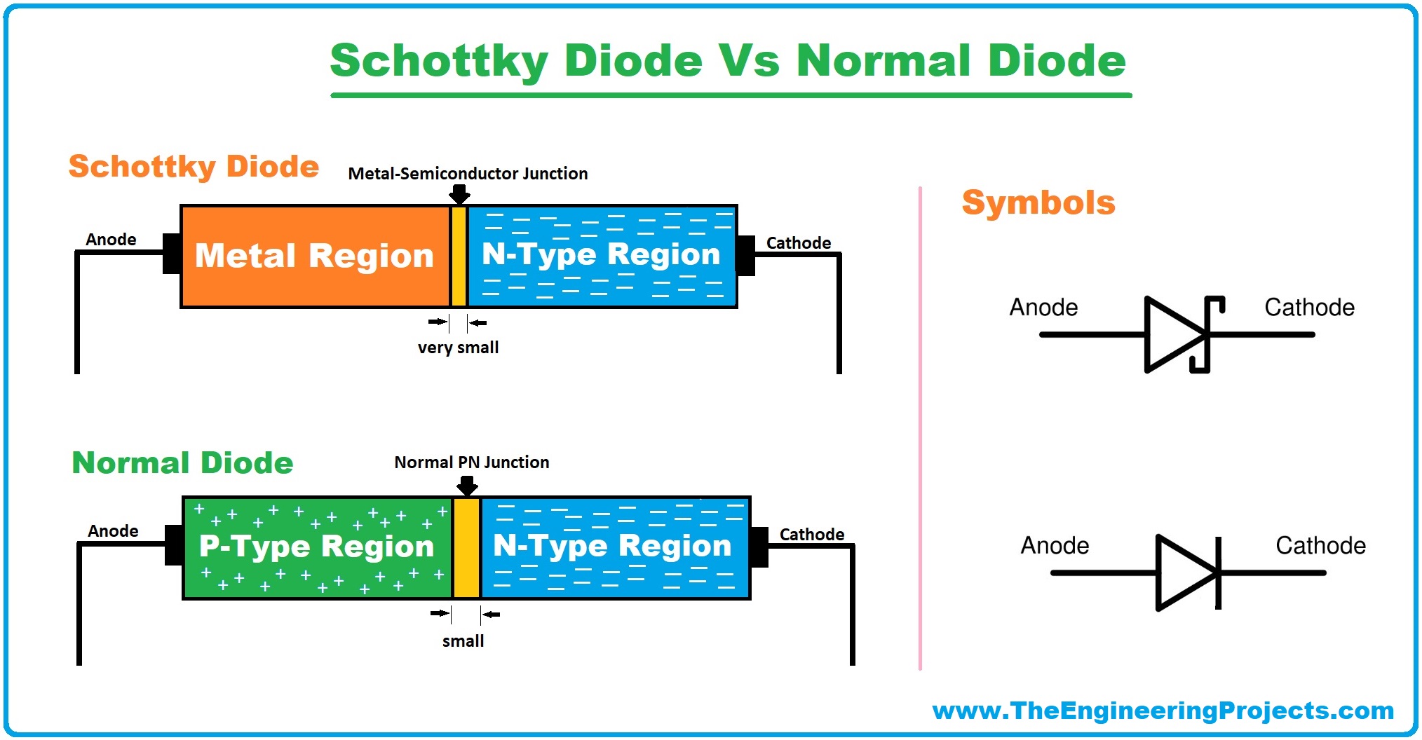
- As we discussed earlier, the PN Junction of a normal diode is composed of a P-type semiconductor and N-Type semiconductor material, while the Schottky Diode has a metal on one side of the junction and an N-Type semiconductor on the other side.
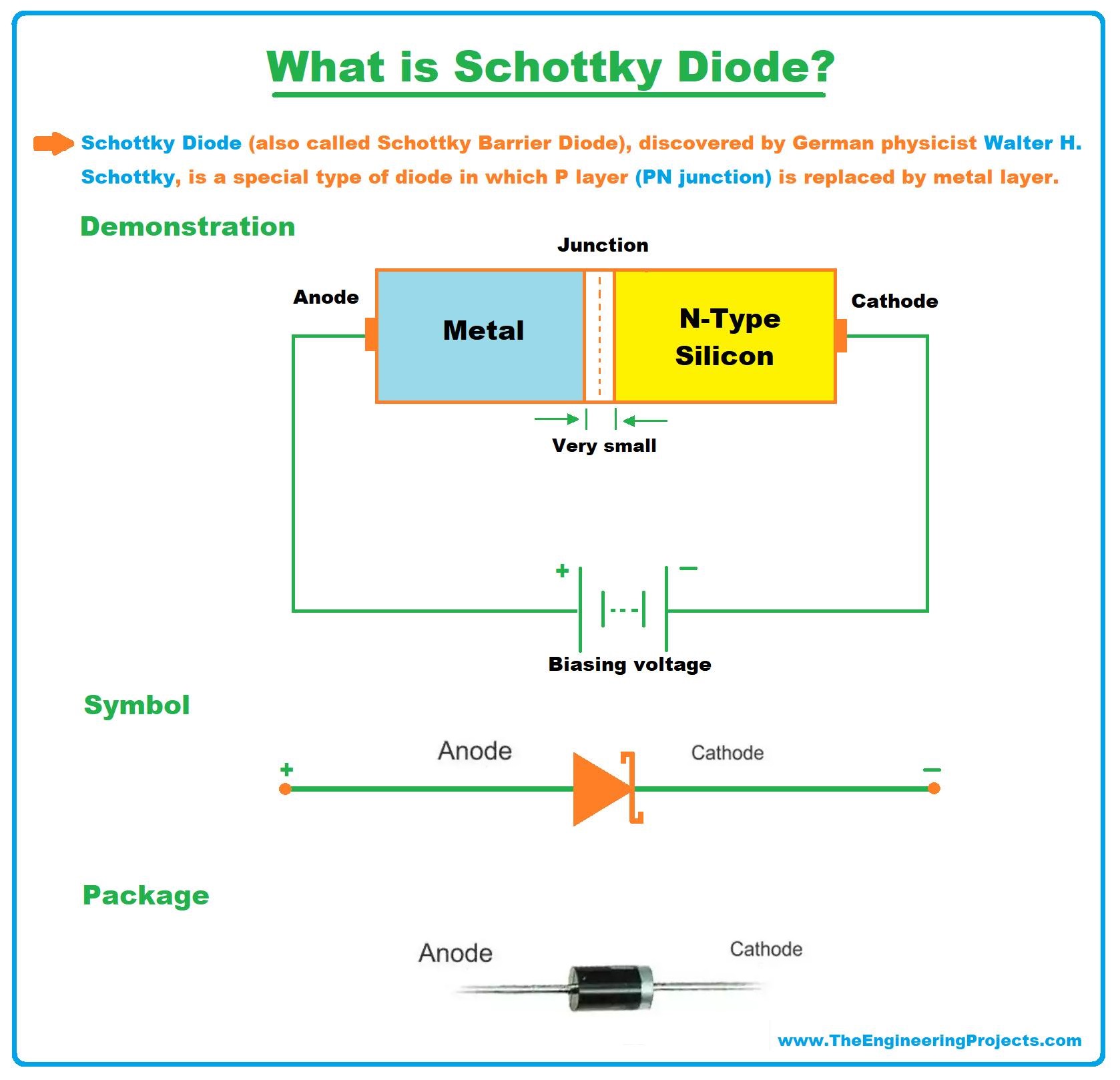
- You can see in the above figure, we have a Metal Region instead of a P-Type Region, so we can say the junction of the Schottky diode is a doping result of metal and semiconductor(Silicon).
- This Metal-to-Silicon Junction generates a potential barrier of 0.15-0.3V, which is 0.7V for a simple diode.
- In Schottky Diode, the number of electrons is greater than the number of holes and thus electrons are solely responsible for the flow of current, and thus termed as Unipolar, while in a normal diode, both holes & electrons are equally responsible for the current flow and thus termed as Bipolar.
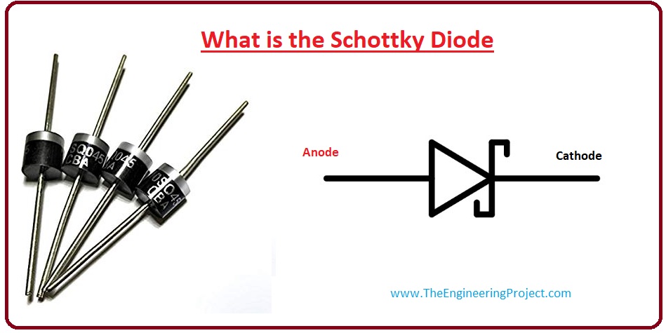
- The Schottky diode symbol is slightly different than that of a normal diode, as it has a slight bend on both sides of the straight bar.
- Examples of Schottky diodes are BAT49 and 1N5711, manufactured by ST Microelectronics.
Why use Metal-to-Silicon Junction?
The Schottky diode has a Metal-to-Silicon Junction instead of a simple PN Junction, which gives it many advantages over a simple diode.
- The potential barrier of a simple PN diode is 0.7V for silicon, which makes it useless for small signals i.e. radio frequency circuits.
- On the other hand, a metal-to-silicon junction develops a potential barrier of around 0.15-0.3V, making it ideal for low-valued signals.
- The potential barrier of a Schottky diode depends on the metal used and the amount of doping in the N-Type region.
- Because of low voltage consumption, its response rate is high and thus used in fast switching applications.
- If we increase the doping of a semiconductor, it will decrease the width of the depletion region, thus lowering the potential barrier.
Schottky Barrier
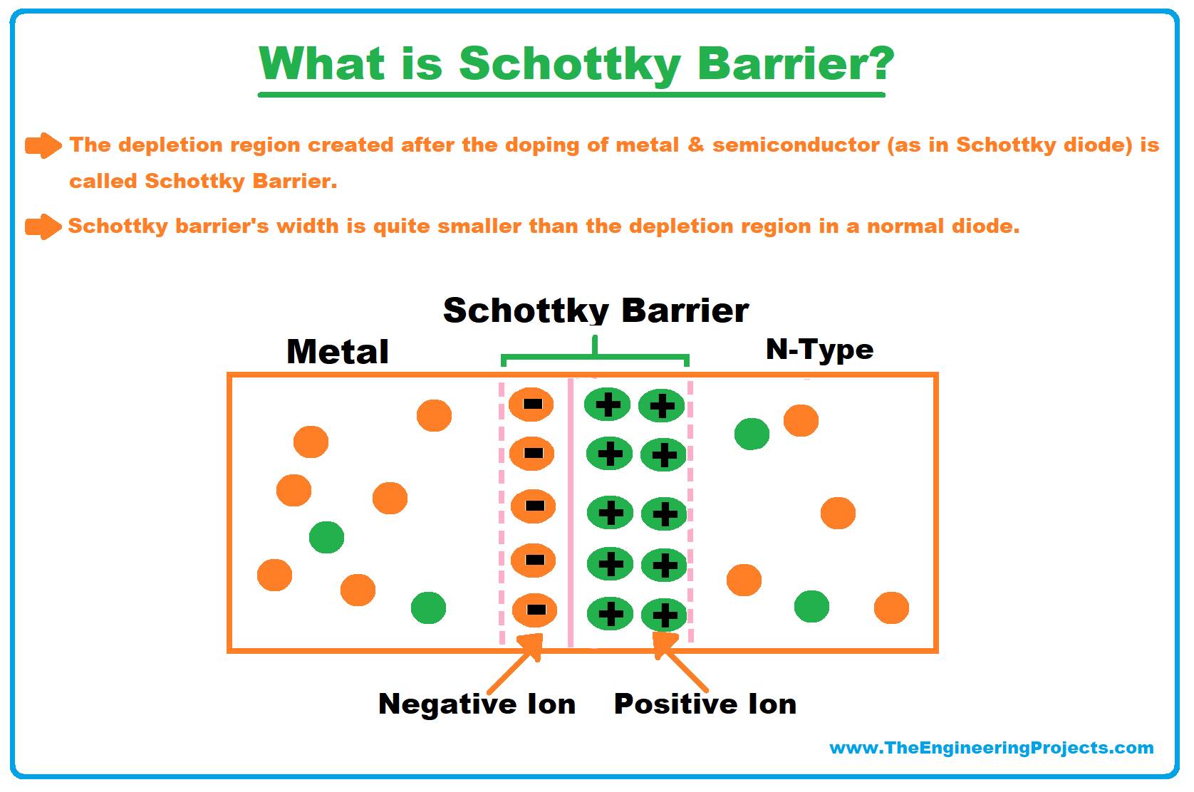
- The depletion region created after the doping of metal & semiconductor (as in the Schottky diode) is called Schottky Barrier.
- In simple words, the Schottky barrier is a minimum Potential Energy required for electrons to cross the barrier.
- Once the P.E. of electrons exceeds a certain limit (depending on doping), they overcome the Schottky barrier and start flowing across the Schottky diode.
- The Schottky barrier's width is quite smaller as compared to the depletion region in a normal diode.
- It normally takes 0.15V to 0.3V to overcome the Schottky Barrier, while for normal depletion regions, it takes 0.6V to 0.7V.
- There are further 2 types of Schottky barriers:
- Rectifying Schottky barrier.
- Non-rectifying Schottky barrier.
Schottky Diode Energy Band
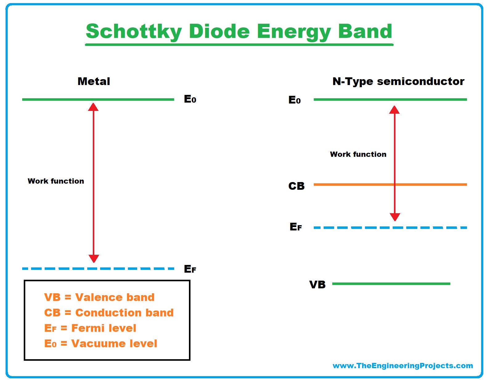
- The potential energy level of electrons outside the material is known as the Vacuum level.
- The amount of energy needed to move electrons from the Fermi level to the vacuum level is known as the work function.
- The value of this energy (work function) is different for metals and semiconductors.
- So the electrons in N-type semiconductors have a larger value of P.E than the electrons in metals.
- Let's see the diagram of the energy band of Schottky diode:
Schottky diode Characteristics Curve
- Now, let's discuss the voltage and current characteristics of the Schottky diode.
- It has low forward voltage loss that's why its characteristic curve is close to current axes as compared to normal diodes.
- When the applied voltage to the Schottky diode exceeds 0.15-0.3V, the diode becomes forward-biased.
- Schottky Diode has a Low Reverse Breakdown Voltage as compared to the normal diode and if this limit exceeds, it may damage the component permanently.
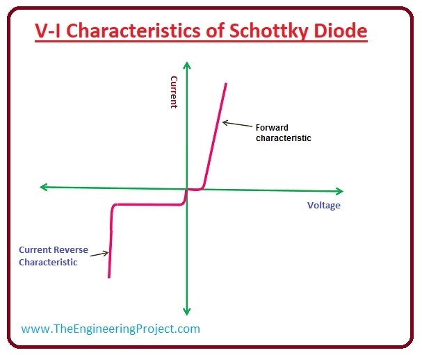
Schottky Diode Vs Normal Diode
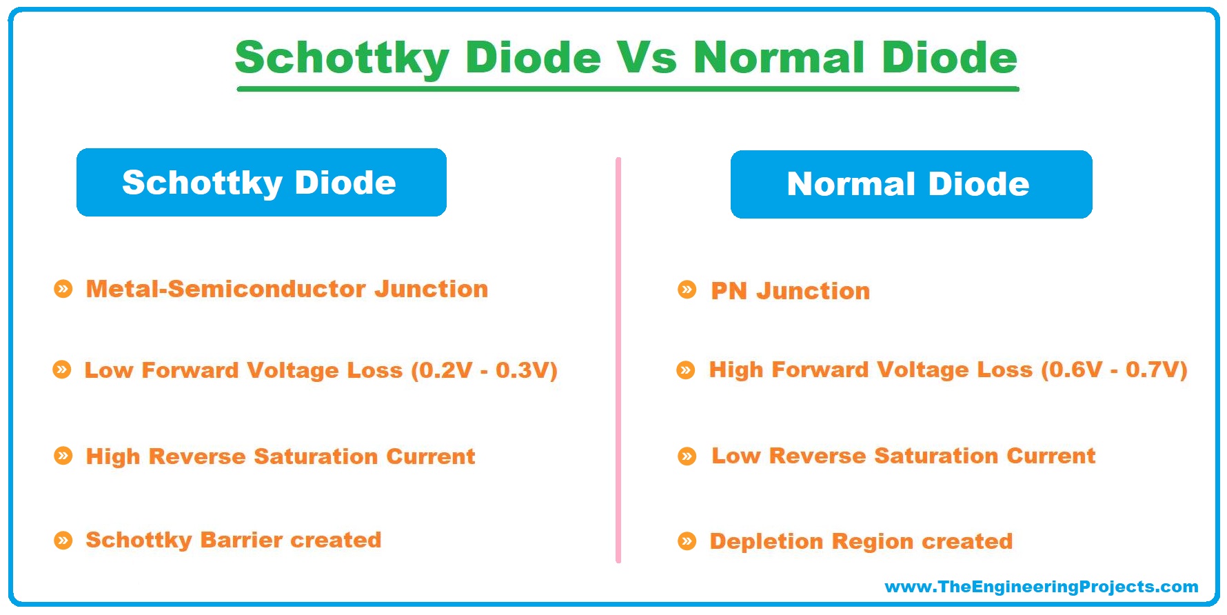
| Schottky Diode Vs Normal Diode | ||||
|---|---|---|---|---|
| No. | Schottky Diode | Normal Diode | ||
| 1 | Metal-Semiconductor Junction | PN Junction | ||
| 2 | Low Forward Voltage Loss (0.2V - 0.3V) | High Forward Voltage Loss (0.6V - 0.7V) | ||
| 3 | High Reverse Saturation Current. | Low Reverse Saturation Current. | ||
| 4 | Schottky Barrier created. | Depletion Region created. | ||
- In the below figure, you can see the difference between Schottky Diode & normal diode:
Schottky Diode Advantages
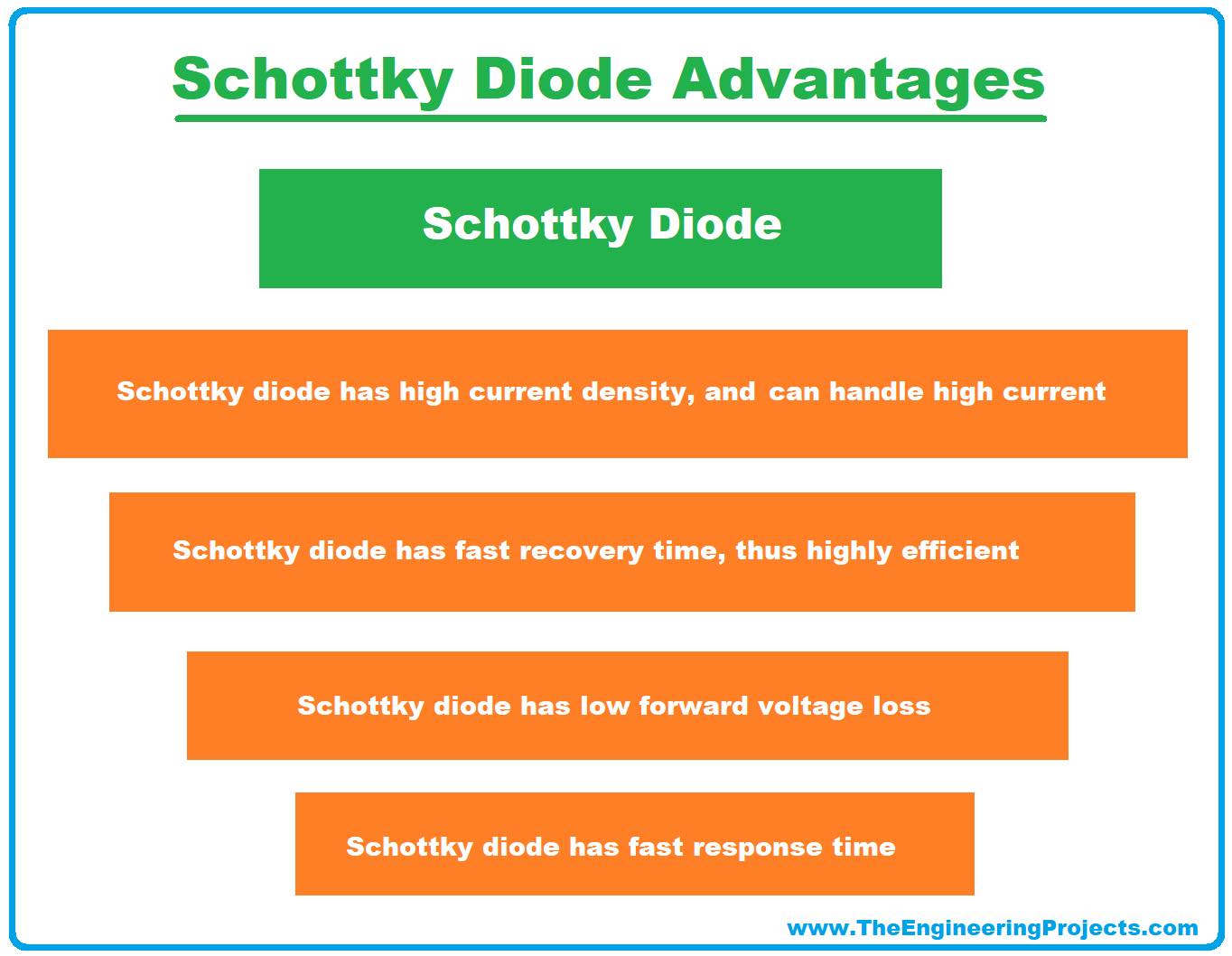
- It has a low forward voltage drop.
- It has a fast response time.
- It has a fast recovery time, thus highly efficient.
- It has a high current density and thus can handle high current at low voltages.
Schottky Diode Disadvantages
- It has a high reverse saturation current.
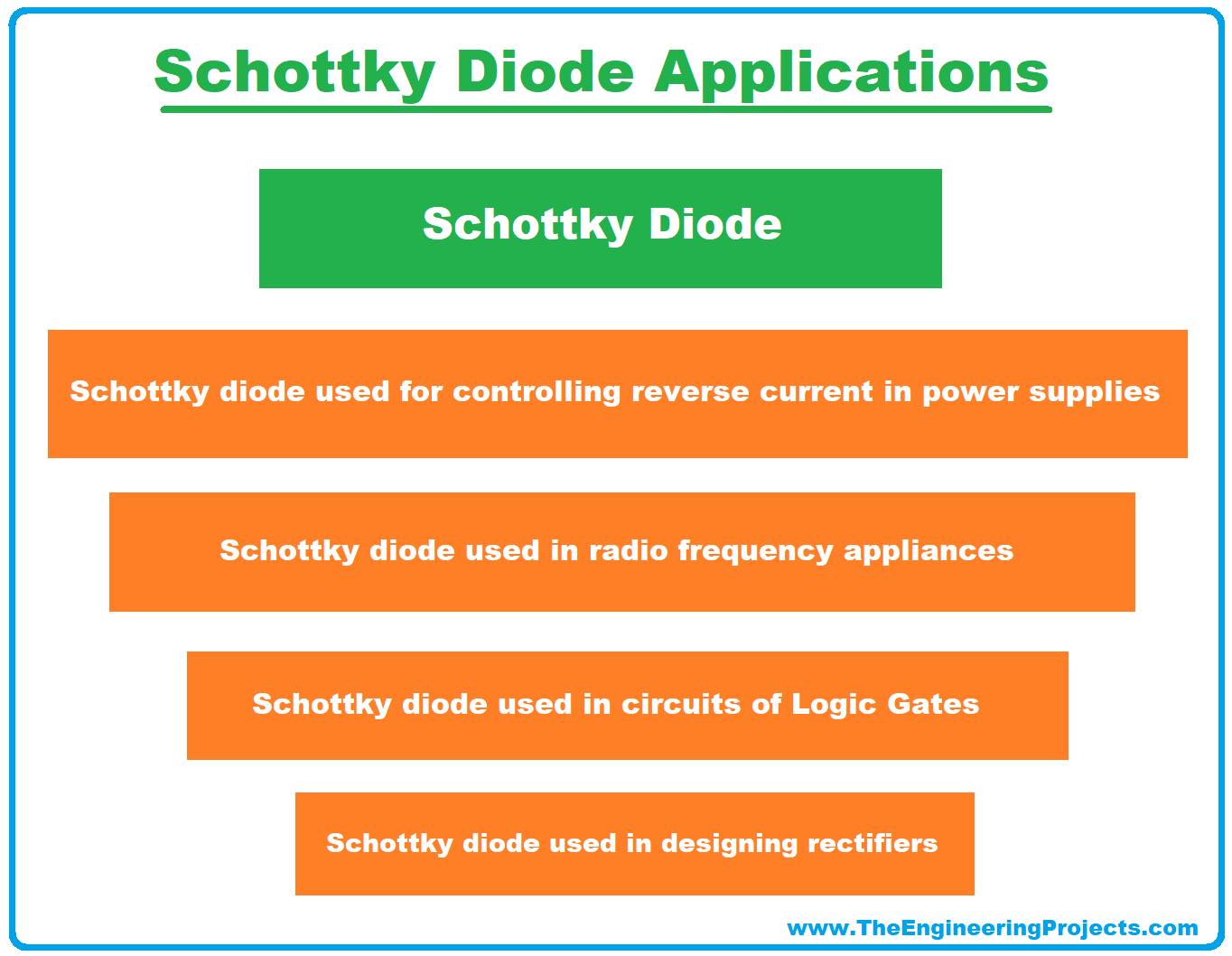
Schottky Diode Applications
There's a long list of Schottky Diode's applications, here I've mentioned a few of them:- It's used in radio frequency appliances.
- It's used in circuits of Logic Gates.
- It's used in designing rectifiers.
- It's used for controlling reverse current in power supplies.


 Semiconductor
 zahidali
 0 Comments


