Arduino 74HC595 Interfacing
- As I told earlier 74HC595 is a serial In Parallel Out Shift Register and is used to increase the output pins of Arduino.
- I am gonna use Proteus software and we will design its simulation and then will check out How it works.
- So, design a simple circuit as shown in below figure:
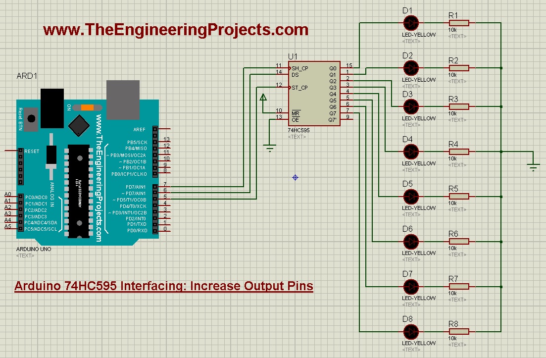
- As you can see in above figure, I have done the following connections between Arduino and HC595:
- Pin # 5 of Arduino ==> ST_CP
- Pin # 6 of Arduino ==> DS
- Pin # 7 of Arduino ==> SH_CP
- All output pins of 74HC595 are connected to LEDs.
- Now upload the below Arduino code and get your hex file.
int RCLK = 5;
int SER = 6;
int SRCLK = 7;

#define TotalIC 1
#define TotalICPins TotalIC * 8

boolean Data[TotalICPins];

void setup()
{
  pinMode(SER, OUTPUT);
  pinMode(RCLK, OUTPUT);
  pinMode(SRCLK, OUTPUT);

  ClearBuffer();
}


void loop()
{
   for(int i = TotalICPins - 1; i >=  0; i--)
   {
      Data[i] = HIGH;
      UpdateData();
      delay(300);
      ClearBuffer();
   }

   for(int i = 1;i < TotalICPins - 1;  i++)
   {
      Data[i] = HIGH;
      UpdateData();
      delay(300);
      ClearBuffer();
   }

}

void ClearBuffer()
{
    for(int i = TotalICPins - 1; i >=  0; i--)
    {
       Data[i] = LOW;
    }
    UpdateData();
}

void UpdateData()
{
   digitalWrite(RCLK, LOW);
   for(int i = TotalICPins - 1; i >=  0; i--)
   {
        digitalWrite(SRCLK, LOW);
        digitalWrite(SER, Data[i]);
        digitalWrite(SRCLK, HIGH);

  }
  digitalWrite(RCLK, HIGH);
}
- The code is quite simple but let me explain it a bit.
- First of all we have given names to our 3 Pins connected to Arduino UNO.
- After that we have made all those 3 Pins as OUTPUT as we are gonna send the data.
- We are using single chip of 74HC595 that's why I have made it 1.
- In the UpdateData function, you can see we have to make RCLK Low and after that we have sent our data.
- But for sending each bit of Data we have to make SRCLK from LOW to High.
- SER is our Serial IN from Arduino to 74HC595.
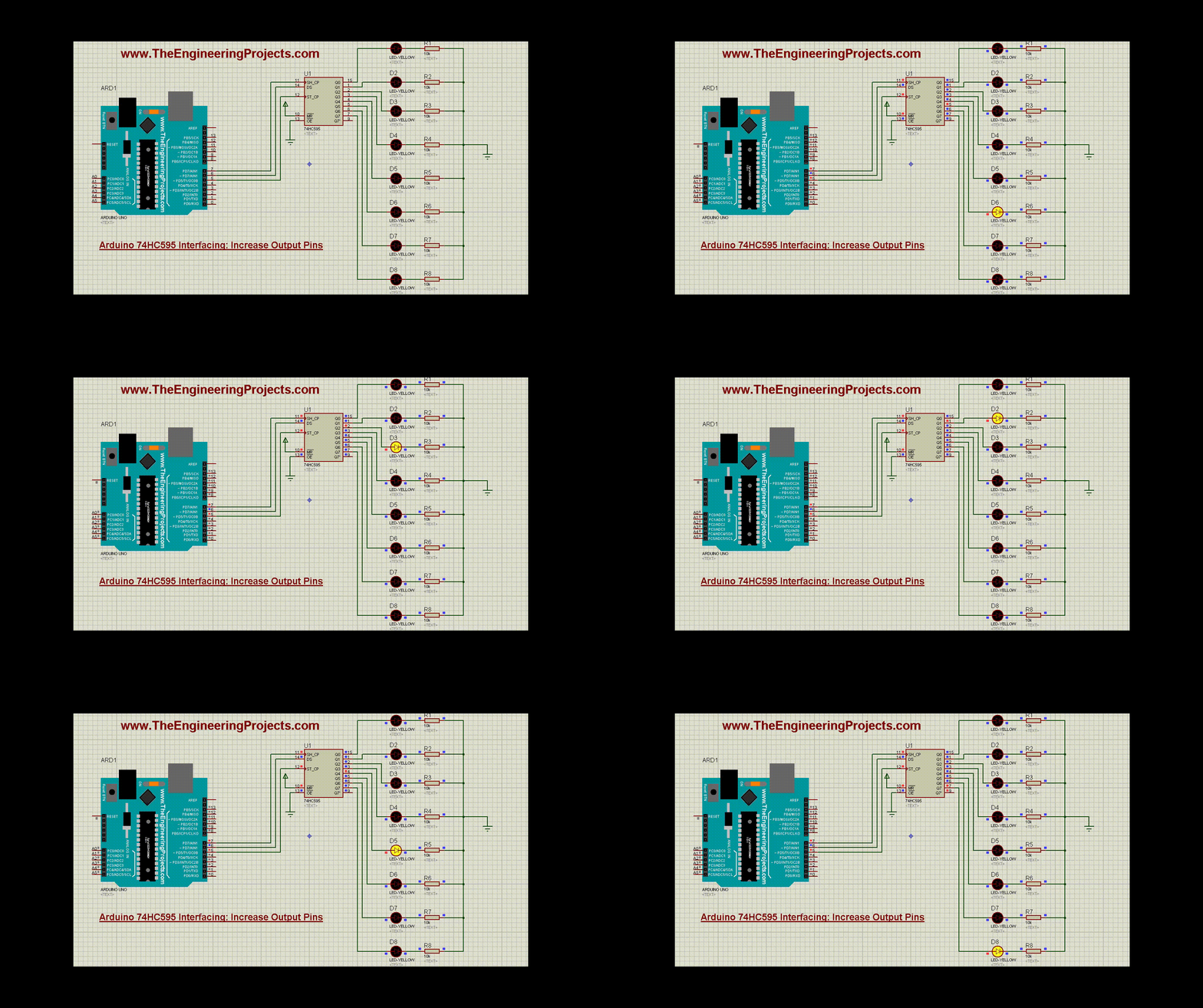
- So, in loop section, I am simply sending HIGH from first Pin to Last and then from last Pin to first and we are getting below results:
- Now let's have a look at How to connect two 74HC595 chips in parallel to increase the output pins to 16.
- I have also given these Proteus simulations for download at the end of this tutorial but I would recommend you to design them on your own so that you got better understanding of this shift register.
Arduino 74HC595 Interfacing: 2 Chips in Parallel
- Now we are gonna place two shift registers in parallel and we will be able to control 16 outputs from single Arduino Pin.
- Although we are using 3 Arduino Pins but the data is sent through Pin # 6 of Arduino and Pin # 5 and 7 are CLK Pins.
- Now design a circuit as shown in below figure:
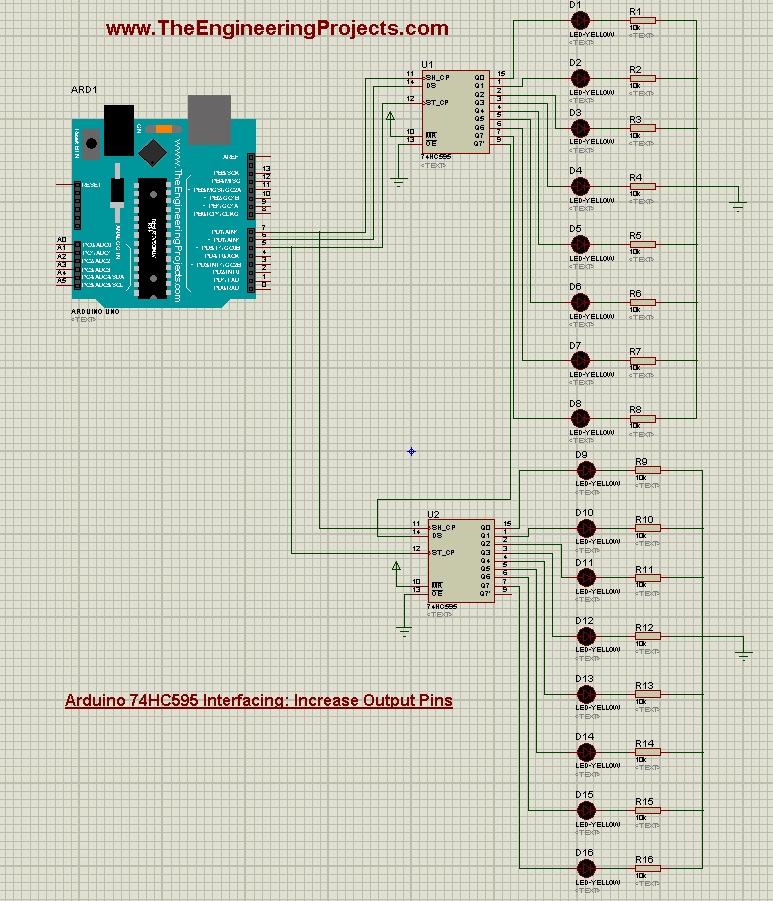
- Now in Arduino Code, you just need to change the TotalIC to 2 and as you have seen we have already multiplied it with 8 so now our for loop will move from 0 to 15.
- Pin # 5 and 7 will simply connected to same pins of second shift register but DS will be connected to Q7' of first shift register.
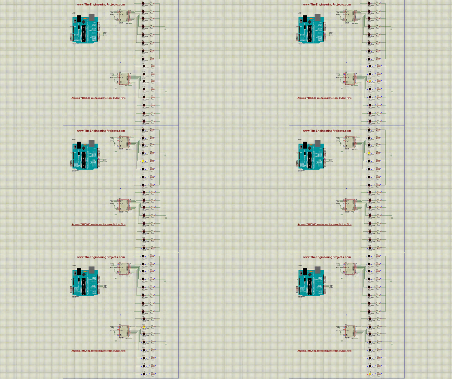
- Now get your hex file from Arduino software and if everything goes fine then you will get something as shown in below figure:
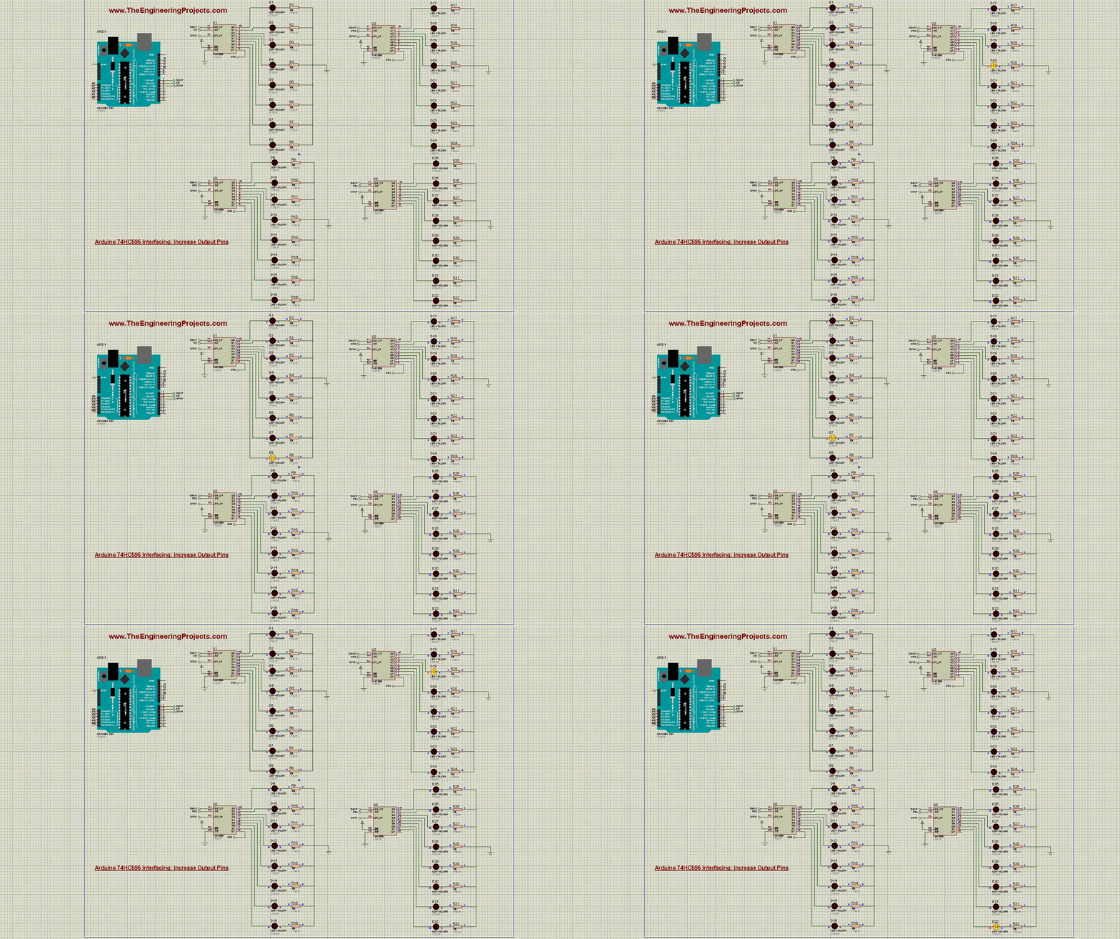
- Now let's make it a bit more complex by adding 4 shift registers in parallel.
- So, design a Proteus Simulation as shown in below figure:
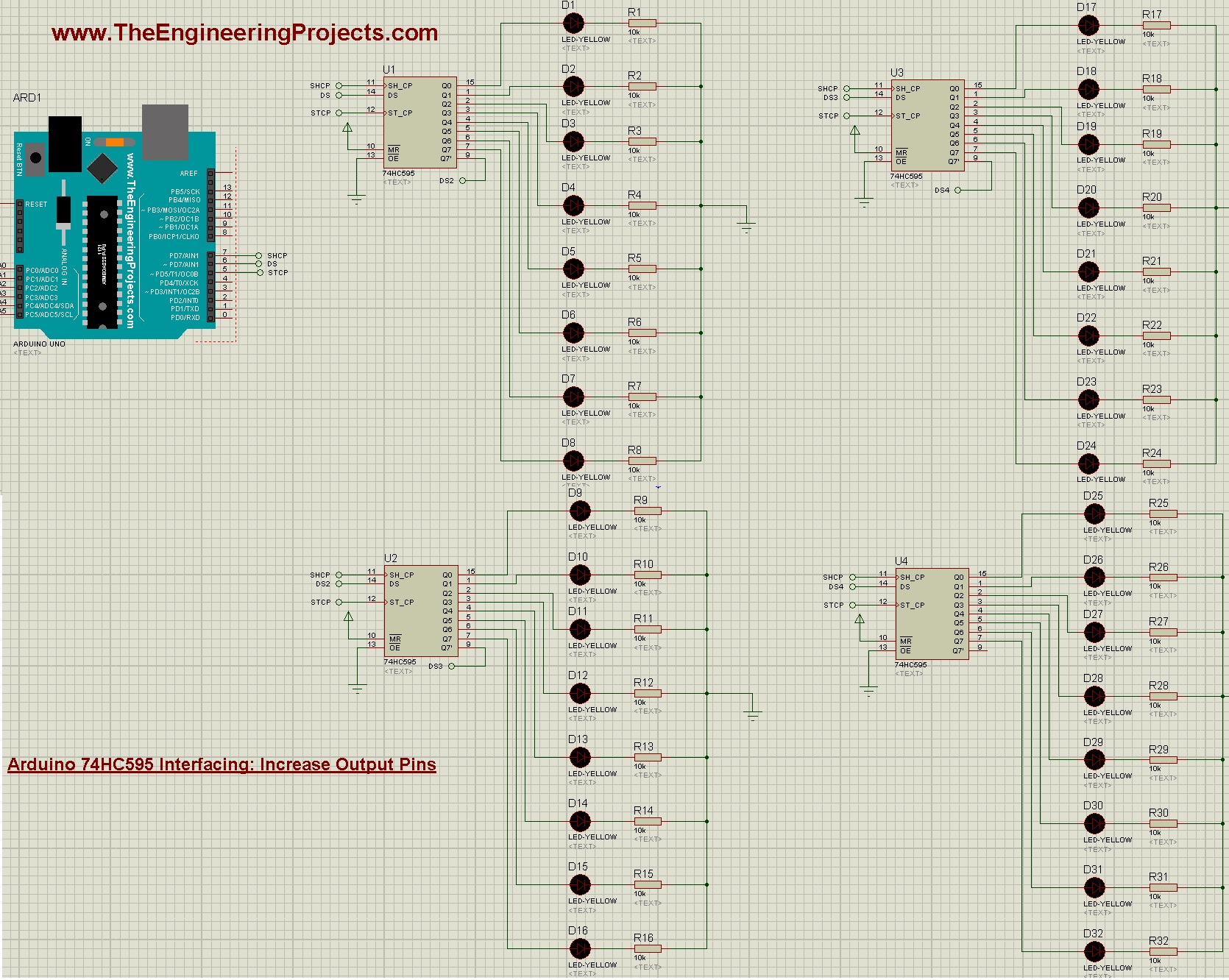
- We have followed the same principal, Q7' of second chip is connected to DS to 3rd chip and goes on.
- I have placed these default Pins instead of connecting the wires, it works the same.
- If this image is not clear then open it in new tab and zoom out to check the connections.
- Now in your Arduino code, you need to change the TotalIC to 4, as now we are using four chips.
- Get your Hex File and run Proteus simulation and if everything goes fine then you will get similar results:

- So, that's How you can quite easily do the Arduino 74HC595 Interfacing and can increase Arduino outputs as much as you want.
- You can download these Proteus Simulations along with code by clicking the below button:
[dt_default_button link="https://www.theengineeringprojects.com/ArduinoProjects/Arduino 74HC595 Interfacing.rar" button_alignment="default" animation="fadeIn" size="medium" default_btn_bg_color="" bg_hover_color="" text_color="" text_hover_color="" icon="fa fa-chevron-circle-right" icon_align="left"]Download Proteus Simulation & Arduino Code[/dt_default_button]
- I have also designed this YouTube video to give you a better understanding of Arduino 74HC595 Interfacing:


