This board is mainly developed for e-textiles and wearables projects. As per the designed purpose, it can be attached to fabric, sensors, power supplies, and actuators. You may need a conductive thread for joining this board with the required object.
In this post, I'll try to cover each and everything related to Arduino LilyPad, what is this about and how it is used for the development of desired projects. Let's jump right in and get down to the nitty-gritty of this board.
| Where To Buy? | ||||
|---|---|---|---|---|
| No. | Components | Distributor | Link To Buy | |
| 1 | Arduino Lilypad | Amazon | Buy Now | |
Introduction to Arduino LilyPad
- Arduino LilyPad is an Arduino Main Board that is mainly designed for e-textiles and wearables projects and is based on the Atmega168/Atmega328 microcontroller.
- LilyPad is nothing but an Arduino-programmed microcontroller and works similar to other Arduino boards available.
- It comes in a round shape unlike other Arduino boards so that it could fit easily in wearables.
- However, the ability of this board to be sewn down with the fabric or sensor through conductive thread puts it ahead and stands out of the boards available in the Arduino community.
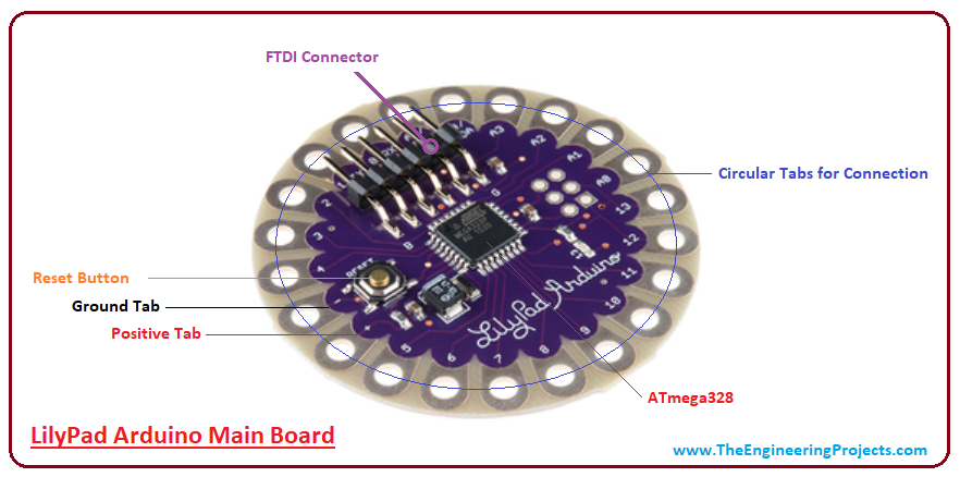
- There are 22 wide open pin-holes, appear around the edge of the whole rounded shape that is mainly used for the connection with the fabric and sensor through a conductive thread.
- Out of these 22 pinholes, one is reserved for +5V, and one for ground.

- The LilyPad Arduino incorporates 6 analog inputs that can also be used as digital I/O. They are marked as A0 through A5 on the board, providing 10 bits of resolution. It is important to note that, the analog inputs measure from ground to 5 volts, however, the upper end of their range can be modified using the analogReference() function.
- The board contains 14 digital pins that can be employed as an input or output, using pinMode(), digitalWrite(), and digitalRead() functions.
- Like other boards in the Arduino, this Pad is programmed by Arduino IDE - an official software mainly used for programming the Arduino Boards, that is developed by Arduino.cc
- The board comes with a wide voltage range and operates anywhere between 2.7 V to 5.5 V. The pins on the board come with the ability to control and handle the input or output of the attached device.
- There are two ways to keep your Pad null and void: increase the operating voltage above 5.5 V or plug the power in reverse order.
- As I mentioned earlier bootloader is used for storing the code and burning it on the board, however, you can also bypass the bootloader and program the ATmega328 using ICSP (In-Circuit Serial Programming) header.
Arduino LilyPad Features
Following are the main features of the Arduino LilyPad.| Microcontroller | ATmega168 or ATmega328V |
| Digital I/O Pins | 14 |
| Analog Input Channels | 6 |
| PWM Channels | 6 |
| Crystal Oscillator | 8 MHz |
| Flash Memory | 16 KB (of which 2 KB used by bootloader) |
| Bootloader Memory | Out of 16KB in the Flash Memory, 2KB is reserved for Bootloader |
| SRAM1 KB | 1 KB |
| EEPROM | 512 bytes |
| Operating Voltage | 2 to 5 V |
| DC Current per I/O Pin | 40 mA |
| Internal pull-up resistor | 20 kO |
Arduino LilyPad Pinout
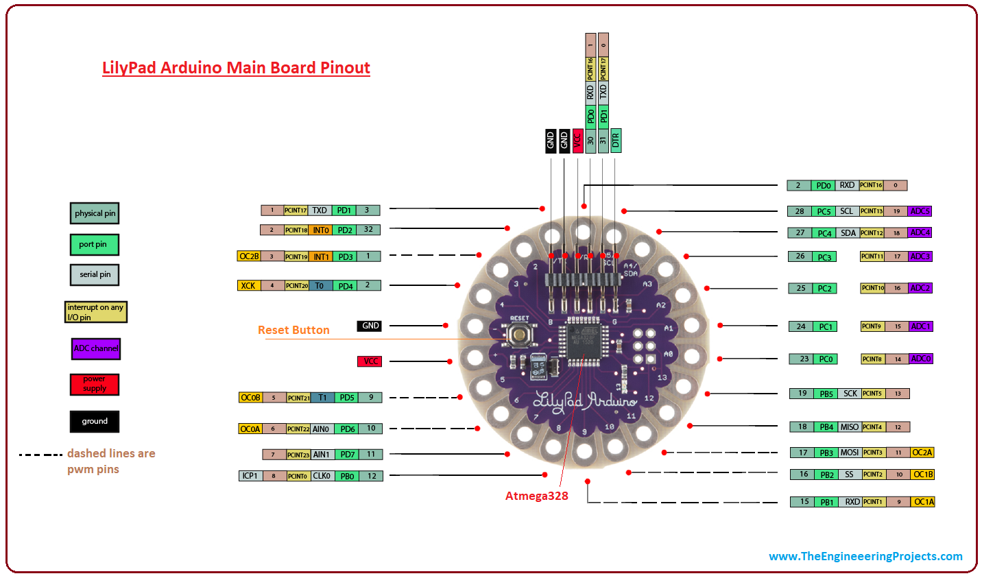
- Arduino Lilypad Pinout is shown in the below figure:

- There is a candid difference between external interrupt pins and PCINT pins. Former is the dedicated hardware pin used for generating the interrupt while later is the interrupt that can be created on any digital I/O pin.
- There are 6 PWM tabs on the board, shown by the dashed lines on the pinout image above. These PWM pins can also be used as digital I/O pins.
How to program Arduino LilyPad?
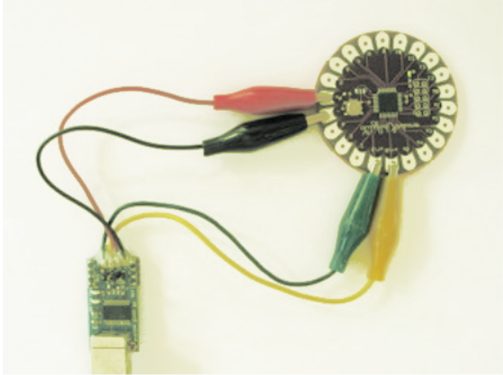
You can layout the LilyPad connection by following the given steps.- Be careful while connecting the power and ground pins of the board. The +5V power must be connected to the positive tab on the board and the ground tab of the board should be connected to the ground of the power source. The reverse connection can cause severe damage to the board and in a worst-case scenario, your board may stop working all at once.
- There are two ways to generate a regulated +5V power source: Using a +5V pin of the Mini USB Adapter or employing another 2.7-5.5V power source using a Lithium rechargeable battery.

- You can see the two circular tabs on the board marked as TX and RX that are mainly used in two ways: For uploading new sketches to the board and establishing a serial communication with other devices.
- Apart from using your own power supply, you can also use Mini USB Adapter or Arduino NG board for connecting the Pad with the computer.
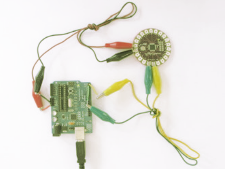
The following figure shows the connection of the Arduino UNO with LilyPad:

Note: Don't forget to remove the ATmega8 or ATmega168 from the NG before connecting it with the LilyPad. You can use alligator clips and jumper wires for connecting the +, -, TX and RX tabs on the LilyPad with the corresponding pins on the NG board.
Applications
- LilyPad is really very handy for e-textile and wearable products, because of its small size.
- Arduino Lilypad is used in IoT products and embedded projects as well.
- The circular tabs covering the whole Pad at the edge are mainly used for the connection between Pad and wearable products.
That's all for today. I hope this read has succeeded in grappling your attention and resonated with your field of interest. If you are feeling dubious in any area of the information related to the Pad that I have left unfolded, you can approach me in the comment section below. I'd love to help you according to the best of my expertise. Keep visiting us for valuable information related to engineering and technology. Thanks for reading the article.


