Introduction to Arduino Due
- Arduino Due is a microcontroller board that is mainly based on Atmel SAM3X8E (32-Bit ARM microcontroller). It is a big module as compared to Arduino Nano or Arduino Uno and comes with more number of pins and memory space as compared to them.
- It contains 54 digital that can work both ways: input or output. Out of these digital pins, 12 can be used to generate PWM outputs.
- This module contains everything in bulk required for the automation project including 12 analog inputs, and 4 UARTs serial module.
- I was floored when I came to know this module comes with clock frequency around 84 MHz. Yes, you heard that right. The splendid oscillator will help in processing speed grow skyrocket.
- Two USB ports are available where one is used as a programming USB Port while other is Native USB Port. Don't you worry, I'll make it clear the difference between them. Just follow along.
- Most of the Arduino Boards run at 5 V but this module is an exception that operates at 3.3V. The pins incorporated on the cannot withstand voltage higher than this. Doing so can drastically affect the board performance and can make your pins null and void.
- JTAG is added on the board that is mainly used for testing the physical connection between the onboard pins.
- The Arduino Due can be programmed using a common Arduino Software (IDE), that is compatible with all Arduino boards and can work both ways: online and offline.
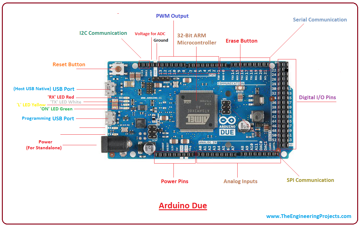
- This module incorporates 2 DAC (digital to analog), 2 TWI, a power jack (you can power up the device by connecting it with a computer through USB cable or using this power jack), an SPI header reset button, an erase button and reset button. Bunch of functions, making your task easy.
- As per the voltage constraint, Arduino shields that operate at 5V are not compatible with this Due module. However, the shields that come with Arduino R3 layout work efficiently including Arduino WiFi shield and Ethernet Shield as they operate at 3.3V.
1. Arduino Due Features
You have got a brief overview of the device. I have compiled the main features of this device at one place. Following table shows the main features of Arduino Due.| Microcontroller | Atmel SAM3X8E ARM Cortex-M3 |
| CPU | 32-Bit |
| Digital I/O Pins | 54 |
| PWM Output | 12 |
| Analog Input | 12 |
| Flash Memory (Program Memory) | 512 KB |
| SRAM | 96 KB (two banks: 64 KB and 32 KB) |
| Operating Voltage | 3.3V |
| Input Voltage | 7-12 V |
| Manufacturer | Arduino.cc |
| Oscillator | up to 84 MHz |
| Software Used | Arduino Software (IDE) |
| Reset Button | 1 |
| Erase Button | 1 |
| DAC (Digital to Analog Converter) | 2 |
| UART (Serial Communication) | 4 |
| SPI Communication | Yes |
| TWI (I2C Communication) | 2 |
| Arduino Shield Compatibility | Yes (that operate at 3.3V) |
| USB (2) | Programming USB (1) Native USB (1) |
| Power Jack | 1 |
| JTAG Header | 1 |
| DC current for 3.3V | 800mA |
| Total DC output current on all I/O lines | 130mA |
2. Arduino Due Pinout
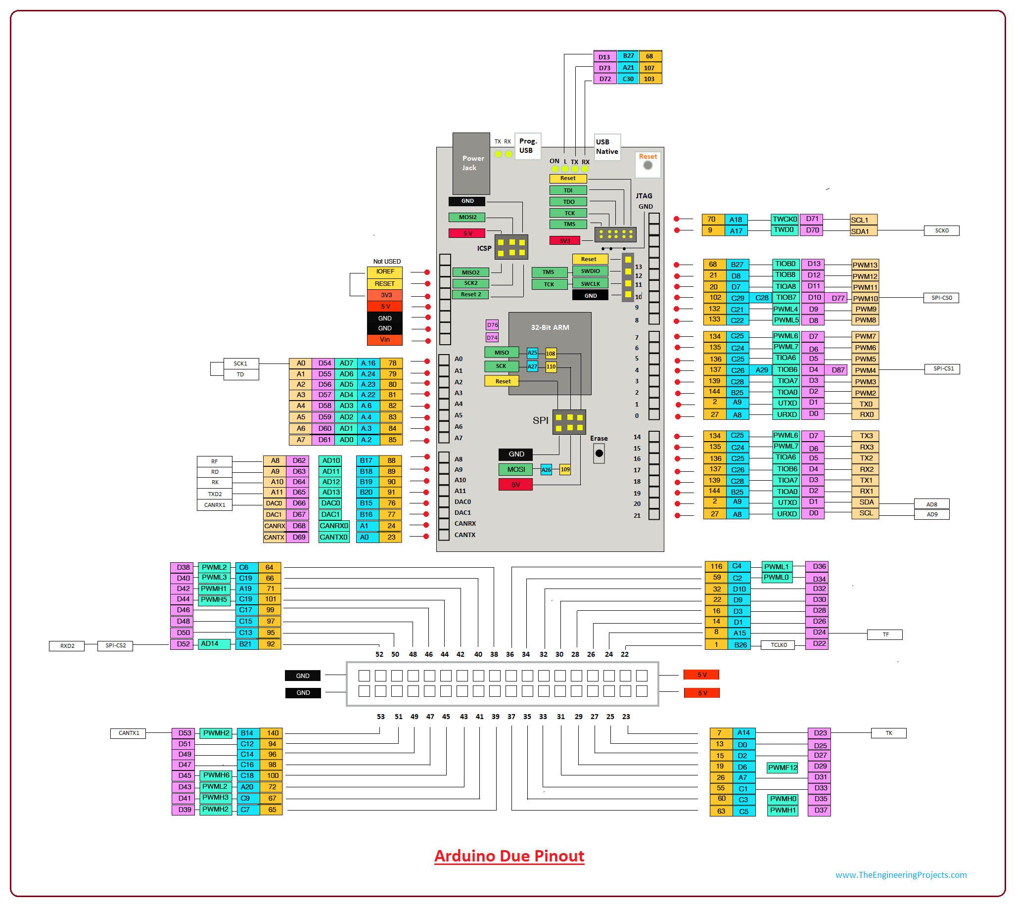
Now, you have got a hold of the main features of this module. In this section, I'll highlight the pinout of the chip. Following figure shows the pinout of Arduino Due.
- I know it is quite overwhelming and difficult to digest at one glance, but don't you worry I have broken it down in the pin description with images.
3. Arduino Due Pin Description
The function associated with each pin will help you understand the purpose of each pin in the relevant project they can be used for. Following table shows the description of each pin.| Digital I/O Pins | 54 | There are 54 digital I/O pins, out of which 12 can be used as PWM outputs. |
| Analog Pins | A0 to A11 | These pins are used for an analog pins on the board. They are 12 in numbers. |
| Digital to Analog Converter | DAC0, DAC1 | Two digital to analog converter with 12bit resolution. |
| Erase Button | 1 | Erases the information by holding down this button |
| Reset Button | 1 | Resets the board |
| External Interrupts | Digital I/O Pins | All 54 pins can be used for generating an external interrupt |
| UART | 4 | Board comes with 4 pairs of TX and RX serial pins for laying out serial communication. These pins include (A9,A8), (D4,D5), (A13,A12), (A11,A10) |
| SPI | Serial Peripheral Communication | (MOSI, MISO, SCK, RESET) Pin used (A26, A25, A27, Reset) |
| TWI | Two Wire Interface (2 module) | There are two I2C communication incorporated on the board with pins at A18, A17, B13, B12 |
| CAN Interface | 2 | CAN (Controller Area Network) Interface is used for communication between controllers. Pins include |
| Power Source | +5V, +3.3V, GND and Vin | +5V- Connected to 5V +3.3V (Operating Voltage) Vin- Input Voltage - Connected to +7V to +12V (recommended) GND - Connected to Ground |
Digital I/O Pins
Arduino Due comes with four ports named PORTA, PORTB, PORTC, and PORTD. There are 54 digitals I/O pins. The pins with PINK color on the pinout mention above are used as digital I/O pins.Analog Pins
There are 12 analog pins on the board. They are a part of PORTA and PORTB and appear on the board as follow.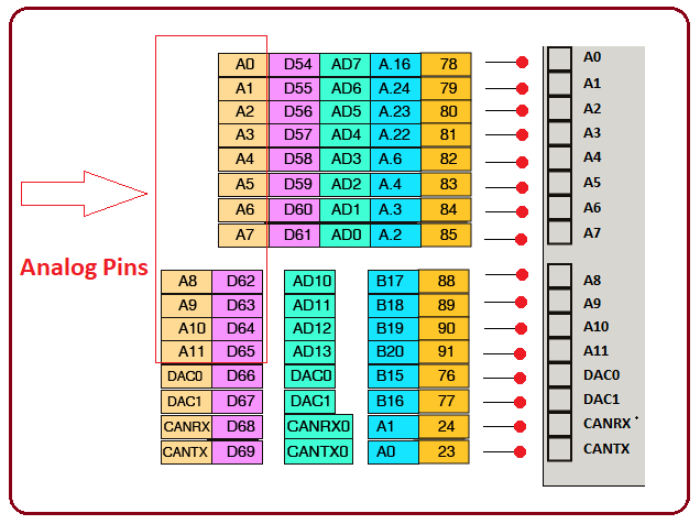
USB Ports and Power Jack
There are two USB ports available on the board where one is programming USB port and other is native USB port. Both ports can be used for programming purpose, however, the native port also acts as a USB host for connected peripherals like keyboards and smartphones. There is one power jack on the board for powering up the device.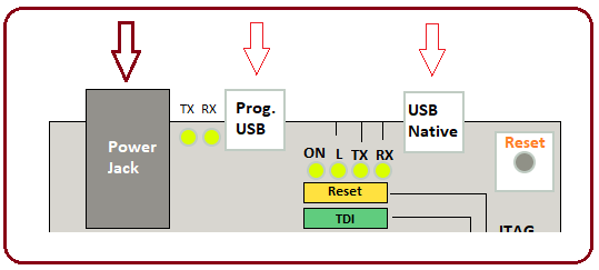
UART
There are four UART channels added on the board. They are used for the serial communication with the external devices where TX is the Serial Transmit Pin while RX is the Serial Receive Pin. They appear on the board as follow.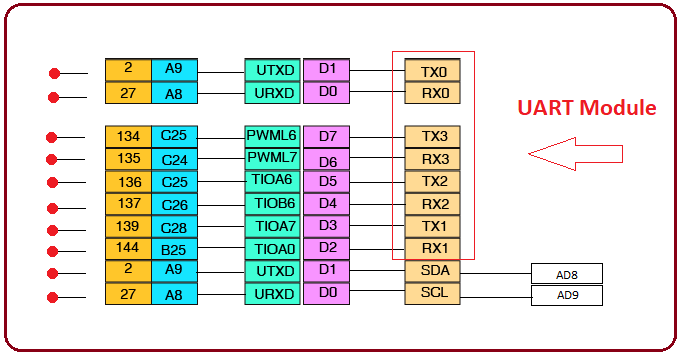
TWI
There are two TWI (Two Wire Interface) modules incorporated on the board, also known as the I2C protocol, and are used to establish the communication between low-speed devices like ADC and DAC converters and microcontrollers. It is a two wire communication and comes with two lines: Serial Clock (SCL) and Serial Data (SDA). The former is a clock signal that is used to synchronize the data transfer between the devices while the later is used to hold the desired data.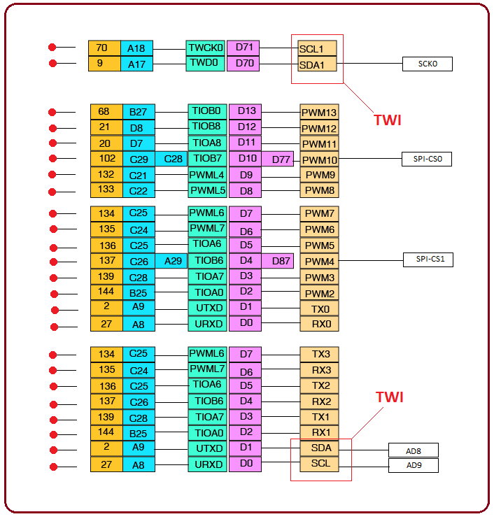
PWM Output
Out of 54 digital pins, 12 are used for PWM output. They appear on the board as follow.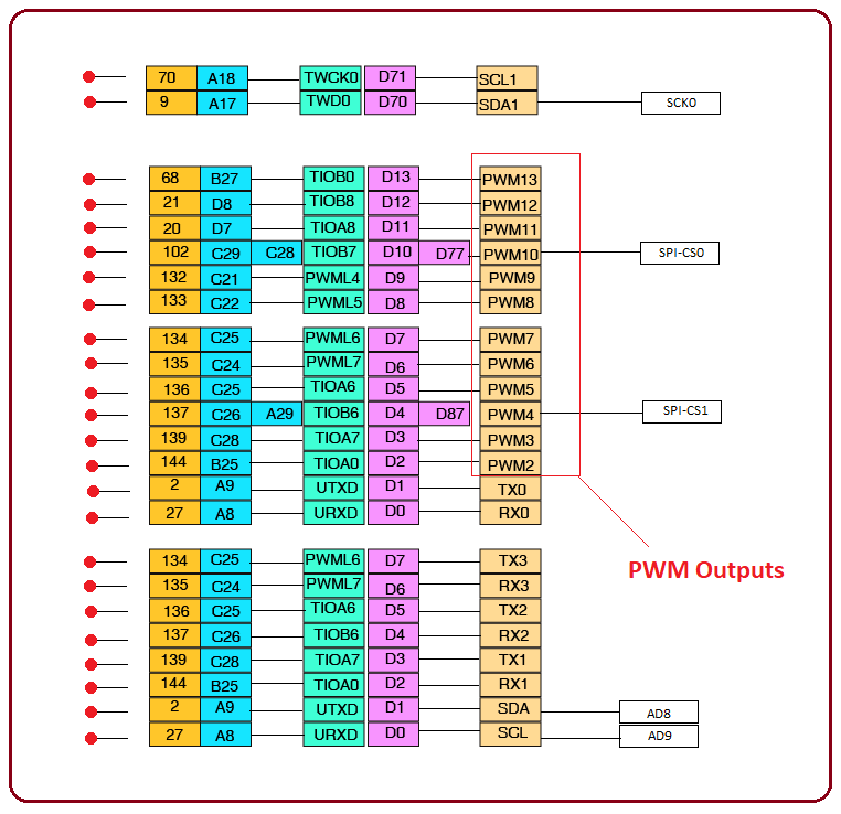
JTAG Header
JTAG header is a remarkable addition in the board that most of the board lack in the Arduino Community. It is a common hardware interface that sets a pathway to communicate directly with external chips on a board. It was introduced by the Joint (European) Test Access Group with the intention of testing the physical connections between pins on a chip. It comes with fours pins known as TCK, TMS, TDI, and TDO. This header incorporates on the board as follows.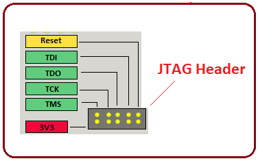
Reset and Erase button
There is one reset and one erase button is added on the device. Former is used to reset the controller while later is used to erase the stored information on the board. They appear on the board as follow.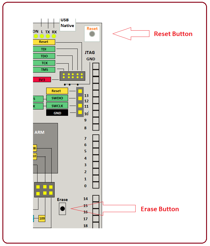
Power Source
There are four power sources mentioned as 5V, 3.3V, Vin and Ground. The 3.3V is the operating voltage of each pin while Vin is the input voltage with the recommended voltage range of 7V to 12V. You can power the controller with Vin or 5V. These voltage sources appear on the board as follow.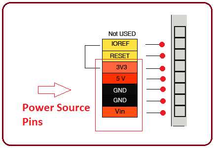
4. Programming and Communication
- Almost all Arduino Boards can be programmed by Arduino Software called IDE. It is easy to use and a common person with no prior technical can learn the software without much difficulty. It is readily available, just download the software and select the board you aim to work on. As I mentioned earlier, no external burner is required to burn the code into the controller. Arduino software works perfectly with common operating systems like Windows, Linux or MAC.
- This module comes with a bunch of communication protocols to communicate with external devices. The UART is useful for setting up a serial communication. One serial module is okay, right? Wrong. There are four of them, giving you the flexibility to establish serial communication with more than one devices. Serial library in the software is mainly used for the serial communication between board and external devices.
- The Serial Monitor is a remarkable addition in Arduino Software, mainly used for transmitting textual data to or from the board.
- The TX and RX pins incorporate an LED on each pin that flashes as the data is transmitted.
- Two Wire Interface is also included in the device that comes with two lines SDA and SCL. There are two TWI channels available on the board. Arduino Software Wire Libary is used to access the TWI bus.
- Arduino Due comes with a serial peripheral interface (SPI) that plays a vital role in the communication between the microcontroller and other peripheral devices such as shift registers and sensors. There are two pins used for SPI communication i.e. MOSI (Master Output Slave Input) and MISO (Master Input Slave Output). The former is used for receiving the data while later helps in sending data by the microcontroller.
5. Difference between Arduino Due and Arduino Mega
There is a vital difference between both modules in terms of operating voltage, memory space, number of pins and processing speed. Arduino Due can perform the functions with greater pace as compared to Arduino Mega. More powerful built-in peripherals and more memory space put Arduino Due ahead of Mega. However, there are some limitations. Arduino Due is not compatible with the 3.3V devices, also, SAM3Xchip provides a complex and intimidating interface that can scare the hell of the person who is practicing this module very first time. It is advised to work with a smaller module like Arduino Uno in the start, and as you get a solid grip on the module, you can move to the complex interface.6. Arduino Due Applications
Arduino Due is a little bit bulky, covers large space and is used in a wide range of applications where fast processing speed is the end result. Following are the main applications of the board.- Industrial Automation
- Home and Security Systems
- Virtual Reality Applications
- Android Applications
- GSM Based Projects
- Embedded System


