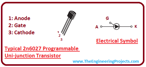
Introduction to 2n6027
- 2n6027 is a programmable uni-junction transistor (PUT) that is widely used in pulse and timing circuits, oscillator, and thyristor-trigger.
- Anode gate availability with this transistor makes it useful for special thyristor applications.
- It is referred as programmable because values like peak voltage Vp and intrinsic standoff ration ? can be programmed using two external transistor.
- 2n6027 comes in four layer construction and contains three junction and three terminals called anode, gate, cathode.
- Current won't be flowing as we bias the PUT properly because gate is positive with respect to cathode. However, PUT will turn ON when we increase the anode voltage and it will allow the PN junction to get forward biased.
- PUT will turn OFF as we decrease the value of anode voltage below cut off.
2n6027 Pinout
2n6027 is a unijunction programmable transistor that consists of three terminals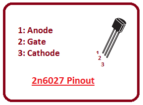
- It is valuable for high volume requirements and comes in sophisticated inexpensive T-92 plastic package.
- It belongs to thyristor family and comes in four layer construction.
2n6027 Internal Block Diagram
Following figure shows the internal block diagram of 2n6027.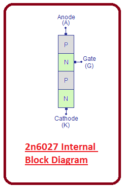
- It is clear from the figure that 2n6027 comes in four layered construction where first layer is P-layer that represents anode.
- The next layer is N-layer which is a gate.
- Third layer is left alone while fourth layer is again P-layer that represents the cathode.
- For external connection, ohmic connections are made on the cathode, gate and anode.
Features
- It encompasses following features
- Low Forward Voltage
- Low Offset Voltage
- Low Gate to Anode Leakage Current
- High Peak Output voltage
PUT Characteristics
Programmable uni-junction transistor characteristics represents the graph between anode current Ia and anode voltage Va.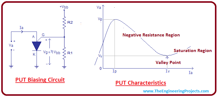
- It is clear from the figure that positive voltage is applied to the anode and cathode is set to ground.
- The junction of two external resistor is connected to gate which constructs a voltage divider circuit.
- Values of two resisters help in determining the peak voltage and intrinsic standoff voltage.
- Anode to cathode voltage is directly proportional to the anode current i.e. when we increase voltage, current will increase and junction acts like a PN junction.
- The point at which anode to cathode Va voltage cannot be increased in called the saturation region. In this region maximum number of charges will be injected in the junction.
- Beyond this point anode voltage decreases and anode current increases. This also represents the negative resistance region and this characteristic can be used in the Oscillators.
- The point at which anode voltage cannot be reduced below minimum value, is called valley point.
- At this point, device will be fully saturated and junction will act like a saturated P-N junction.
- The point at which anode to cathode voltage enters the negative resistance region is called peak voltage. Peak voltage can be represented in the following equation.
Vp = 0.7V + Vg = 0.7V + VR1 = 0.7V + ?Vbb
- Here ? represents the intrinsic standoff ratio. and Vbb represents the total voltage houses in external resistor network.
- Intrinsic standoff ration is the ration between R1 and the sum of R1 and R2. It will determine how much voltage will drop across cathode and gate terminal of PUT.
- ? = R1/R1+R2
Absolute Maximum Ratings
Following figure shows the absolute maximum rating of uni-junction programmable transistor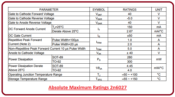
- Absolute maximum rating are also known as stress ratings.
- It is important to note that values given above are standard values.
- If values are exceeded from given value it can damage the device at large.
- If stresses are extended from the given operations conditions, they can harm the device reliability.
- Duty Cycle = 1%
- Anode positive, RGA=1000 ohms
- Anode negative, RGA=Open
Applications
- 2n6027 is widely used in oscillator circuits.
- It is used in pulse and timing circuit.
- It can be used as a thyristor-trigger.


