Arduino PWM, how to use arduino pwm, pwm arduino, pwm pins in arduino
Hello friends, I hope you all are doing great. In today's tutorial, I am going to show you How to use Arduino PWM Pins. It's the next tutorial in our new Arduino Tutorial for Beginners series. We will design a small code in which we will be controlling a dc motor's speed using the Arduino PWM Pins but before going into the details, let me first give you an introduction to Arduino PWM Pins because without understanding the PWM, which is the abbreviation of Pulse Width Modulation, you won't be able to understand How to use Arduino PWM Pins. In our previous tutorial, we have seen How to use analogWrite in Arduino and I have told you in that tutorial that we use this command for PWM as well. So, today we will have a look at How to do that. PWM is an abbreviation of Pulse Width Modulation, its a simple technique in which we just modulate the width of a pulse to get our required results. Suppose, we have a 12V DC signal but my requirement is to get the 6V instetad of 12V so here what I need is PWM. I will use PWM on 12V signal and then reduce it to 6V. Another important thing related to PWM is duty cycle. Duty Cycle is the percentage for which the pulse remains HIGH. For example, if the pulse is of 12V and you turn it into 6V using PWM then the duty cycle of PWM is 50%. I have posted many tutorials on PWM for example you should have a look at How to Generate PWM in 8051 Microcontroller. In this tutorial, I have explained in detail about PWM signal. Moreover, you can also have a look at DC Motor Speed Control using Arduino in which I have controlled the speed of DC Motor with LDR Sensor. Anyways, let's get back to How to use Arduino PWM Pins:

How to use Arduino PWM Pins ???

  • You can download the complete simulation along with its Arduino code for Arduino PWM by clicking the below button:

Download Simulation & Cod

  • First of alll, we should know which pins of Arduino can be used for PWM purposes.
  • So, if you have a look at the below figure, its an Arduino UNO and all the pins of Arduino UNO which has this sign "~" in front of them are PWM pins.
Arduino PWM, how to use arduino pwm, pwm arduino, pwm pins in arduino
  • If you have a look at the above Arduino UNO image then you can see that "~" this sign is placed in front of six pins.
  • So, Arduino UNO PWM Pins are:
  • Pin # 3
  • Pin # 5
  • Pin # 6
  • Pin # 9
  • Pin # 10
  • Pin # 11
  • Using these PWM Pins, you can create the PWM pulse which we are gonna do rite now. :)
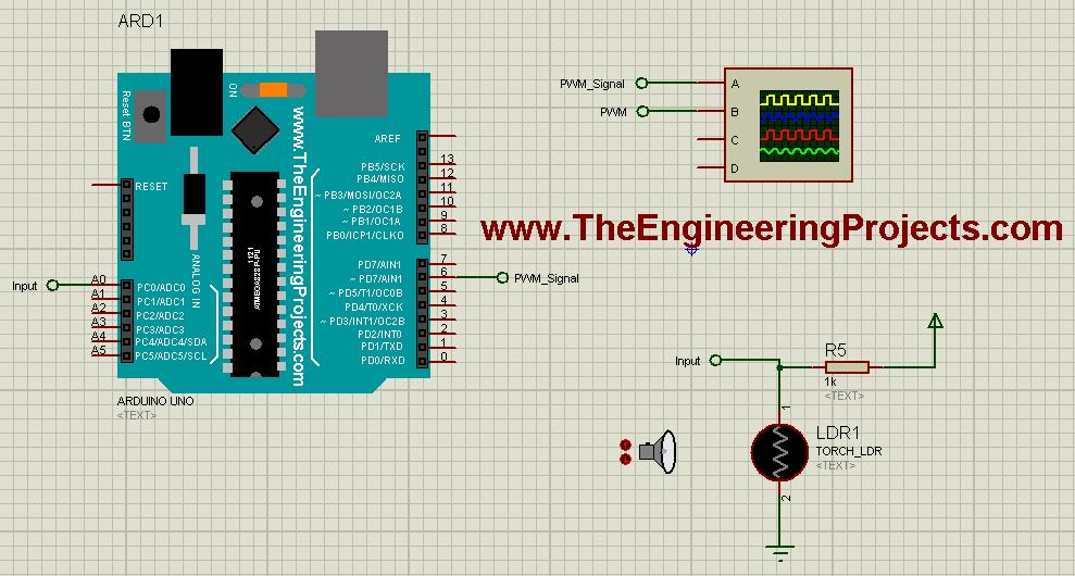
  • So, design a simulation in Proteus as shown in the below figure:
Arduino PWM, how to use arduino pwm, pwm arduino, pwm pins in arduino
  • As you can see in the above figure that I have used LDR Sensor with Arduino UNO and I have plotted the PWM output coming from Arduino UNO on the oscilloscope.
  • For PWM output the command used in Arduino is:

analogWrite(PWM_Pin, PWM_Value);

  • As, you can see its just an analog Write command and using it you can write any value to the PWM Pin ranging from 0 to 255.
  • At 0 the duty cycle of PWM will be 0% and at 255 it will be 100%.
  • So, what I did in the above example is I just take the analog value coming from LDR and then transferred it to PWM Pin of Arduino UNO.
  • So, now upload the below code in your Arduino board:
int PWMControl= 6;
int PWM_Input = A0;

int PWM_Value = 0;

void setup() {
    pinMode(PWMControl, OUTPUT);
    pinMode(PWM_Input, INPUT);
    Serial.begin(9600);
}

void loop() 
{
    PWM_Value = analogRead(PWM_Input);
    PWM_Value = map(PWM_Value, 0, 1023, 0, 255);
    analogWrite(PWMControl, PWM_Value);
}
  • So, now Get your Arduino Hex File and upload it in your Proteus software.
  • You will also need to download Arduino Library for Proteus, if you wanna use this Arduino UNO in Proteus.
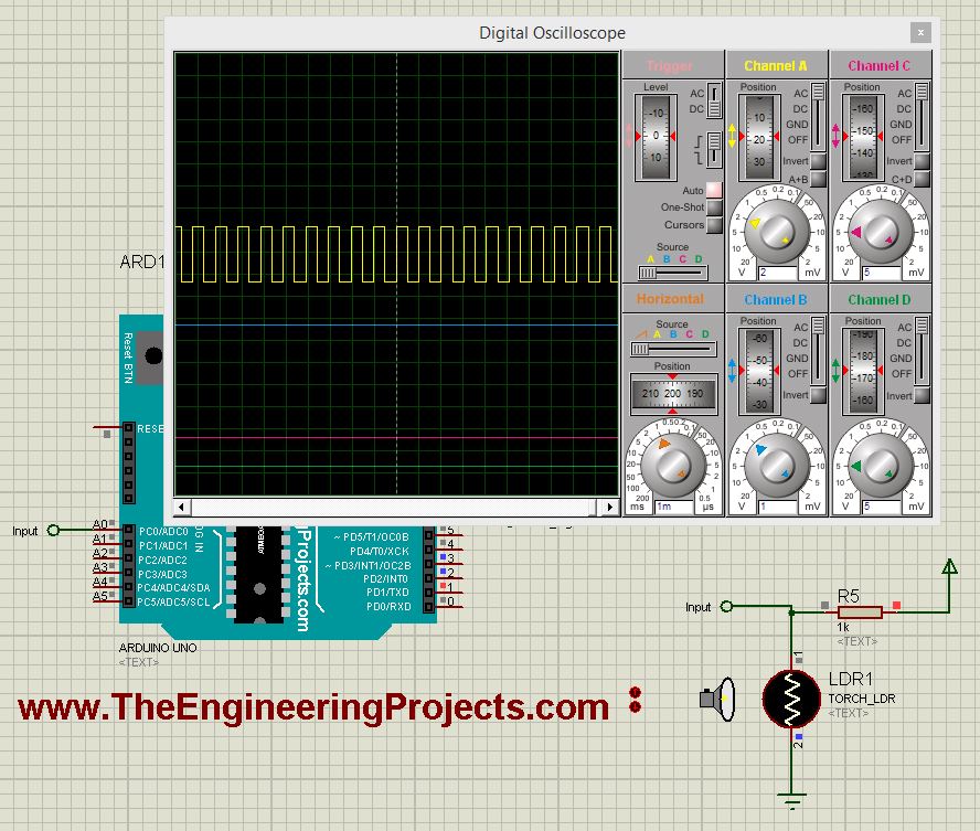
  • Now, if everything goes fine then you will get results as shown in below figure:
Arduino PWM, how to use arduino pwm, pwm arduino, pwm pins in arduino
  • Now you can see in the above figure that I have shown the PWM pulse in the oscilloscope and now when you change the LDR value then this pulse's PWM will also change.
  • You can download the complete simulation with Arduino code by clicking the button above.
  • If you have any problems or issues in this Arduino PWM tutorial then let me know in comments.
I hope you have enjoyed today's post on Arduino PWM Pins and I would suggest you to have a look at DC Motor Speed Control using Arduino, it will help you a lot in understanding the basic concept of Arduino PWM. So, that's all about Arduino PWM, will see you guys in the next tutorial. Till then take care and have fun !!! :)