
Servo Motor Control using myRIO


Servo Motor Control using myRIO
Servo Motor is a device with a small output shaft. It has three input terminals. Two terminals are for the power supply and the third is for sending the servo coded signal. The electrical or electronics projects where there is a need of motion, servo will be the best option in this case. The shaft of the servo motor changes its position corresponding to the servo coded signal applied at its input. It has a wide range of applications including robotics, automated baby cradle, solar tracking systems, elevators etc. Servo motor is shown in the figure given below.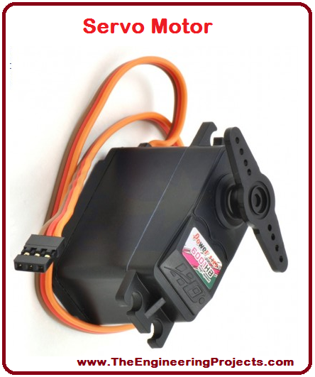
- Servo Motor Control with PIC Microcontroller
- Angle Control of Servo Motor using 555 Timer
- Control Servo Motor with Arduino in Proteus
- Servo Motor Control using Arduino
1. Servo Motor Pins
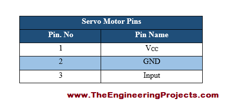
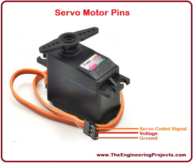
- Servo motor has three pins, two for the power supply and one for sending servo coded signal.
- These three pins are listed in the table given in the figure shown below.
- Servo motor along with its pins is shown in the figure given below.
2. Servo Motor Pins Description
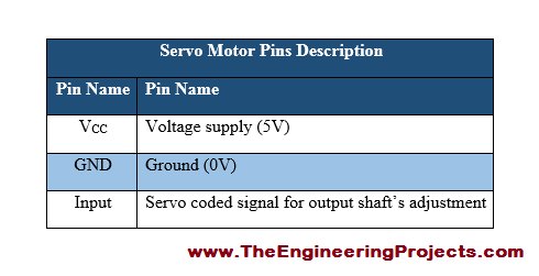
- We must know the function of each pin of any electronic device.
- Pin functions of all the pins are provided in the table shown in the figure given below.
3. Servo Motor Dimensions
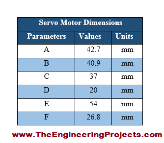
- In the figure shown below, servo motor is divided into different segments e.g. A, B, C etc.
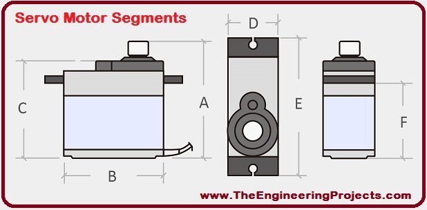
- The dimensions of each segments are provided in the table given in the figure shown below.
4. Servo Motor Specifications
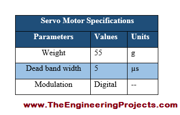
- Specifications are such parameters on the basis of which a device can become more popular.
- Servo motor specifications are listed in the table given in the figure shown below.
5. Servo Motor Ratings
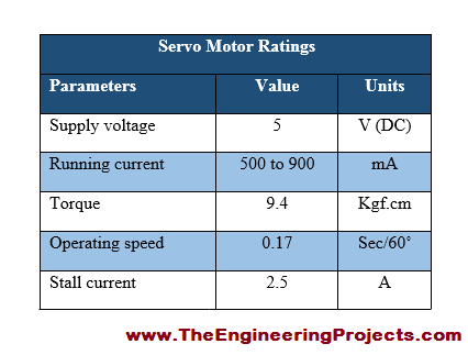
- The power requirement of any device can be estimated through its ratings.
- Servo motor ratings are given in the table shown in the figure below.
6. Servo Motor Applications
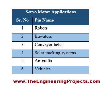
- Servo motor has a wide range of real life applications.
- Some of them are listed in the table given in the figure shown below.
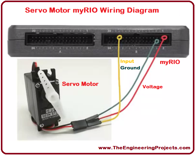
7. Servo Motor Control using myRIO Wiring Diagram
- I have made a completely labelled wiring diagram for servo motor control using myRIO.
- A complete wiring diagram is given in the figure shown below.

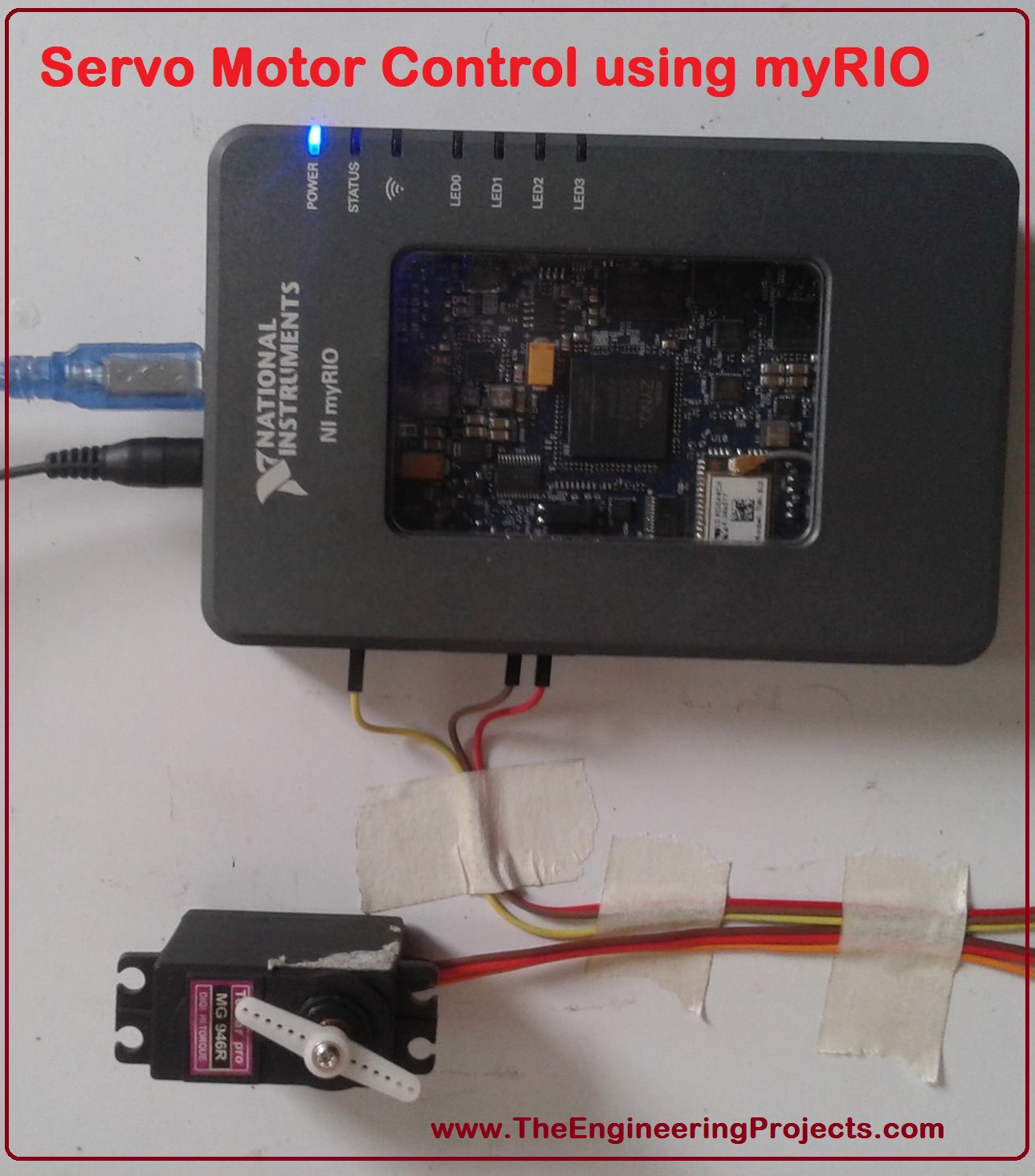
8. Servo Motor Control using myRIO Actual Wiring Diagram
- The actual wiring diagram for servo motor control using myRIO is shown in the figure given below.
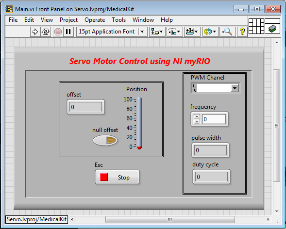
9. NI LabVIEW Complete Front Panel Window
- The complete front pane; window for servo motor control using myRIO is given in the figure shown below.
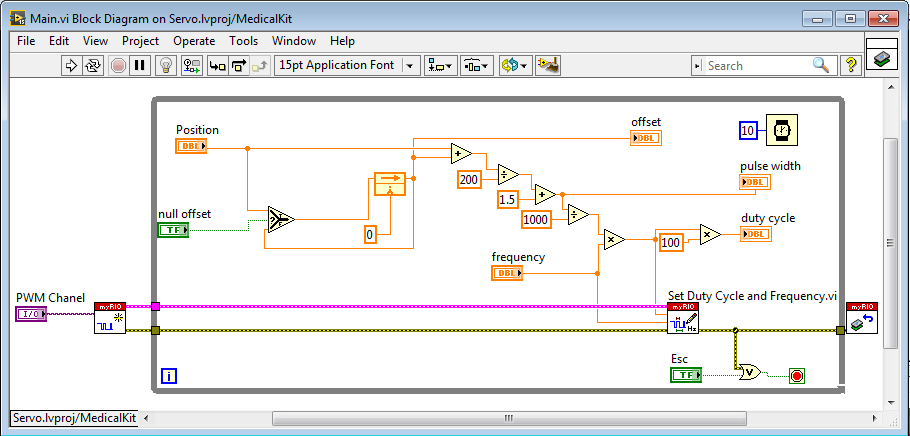
10. NI LabVIEW Complete Block Diagram Window
- The complete Virtual Instrument (VI) for servo motor control using myRIO is shown in the figure given below.
- You can download the wiring diagram for servo motor control using myRIO and the complete LabVIEW VI, just by clicking on the button below.
×
![]()


 1 user


 Continue Wishlist


 Getting Started Guide
 Help Center
 Contact us
 Doist Blog
 Privacy
 Security
 Terms of Service
 What's new: Channel Descriptions


 LabView Tutorials
 syedzainnasir
 2 Comments


 2.3k
2.3k
 953
953
 921
921
 2.1K
2.1K
 servo Motor Control using myRIO
servo control through myRIO
servo motor control via myRIO
servo motor interfacing with myRIO
how to control servo motor using myRIO
how to interface servo motor with myRIO
servo motor myRIO interfacing
Interfacing of servo motor with myRIO

 Tuesday, August 29, 2017