Introduction to 2N3904


Introduction to 2N3904
- 2N3904 is a silicon NPN Bipolar Junction Transistor (BJT), enclosed in TO-92 package and is normally used for switching & amplification purposes.
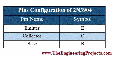
- 2N3904 Pinout consists of 3 Pins i.e. Base, Emitter & Collector.
- As it's an NPN transistor, so major charge carriers are electrons caryying negative charge.
- Small voltage at base(around 0.7V) changes its state from reverse to forward biased and starts conducting.
- It has a wide range of applications i.e. used in televisions, home appliances, medium-load switches, PWM applications etc.
2N3904 Pinout
- 2N3904 Pinout has three pins in total:
- Emitter denoted by E
- Base denoted by B.
- Collector denoted by C.
- 2N3904 Pin Diagram is shown in below figure:
- 2N3904 Pinouts alongwith their symbols are shown in the table given below.
2N3904 Datasheet
- In order to get in-depth knowledge on any component, must read its datasheet. Here's the link to download 2n3904 Datasheet:
2N3904 Equivalent
Although common transistors such as 2N3904 are easily available in local/online electronics stores, but its wise to know the alternatives. So, 2N3904 equivalents are as follows:- BC636
- 2N3055
- 2N2222
- BC549
- BC639
- 2SC5200
- 2N2369
- 2N3906
2N3904 Ratings
- Transistors are available in different ranges of power ratings and their selection depends on circuit's requirements.
- So, a circuit designer's task is to select an optimized transistor for its circuit, which should fullfill all its power equirements & must be cost efficient.
- If current/voltage passing through a transistor exceeds its ratings, the transistor may burnt out.
- Below table shows 2N3904 Ratings:
| 2N3904 Ratings | ||||
|---|---|---|---|---|
| No. | Parameter Name | Parameter Value | ||
| 1 | C-E Voltage (VCEO) | 40V (DC) | ||
| 2 | C-B Voltage (VCBO) | 60V (DC) | ||
| 3 | E-B Voltage (VEBO) | 6V (DC) | ||
| 4 | Collector Current (IC) | 200mA | ||
2N3904 Applications
2N3904 is one of the most commonly used NPN transistor because of its low-cost, high-speed and small-size. Few of 2N3904 applications are as follows:- It's normally used as a simple switch to control heavy loads, because of its low saturation voltage and high gain.
- It's used in home appliances i.e. TV, LCDs, stereo systems etc.
- It's also used in fast switching applications i.e. pulse width modulation(pwm), because of its fast switching speed.
- 2N3904 is also in signal amplification projects(i.e. sound amplifiers) as it has high current gain & thus can be used as an amplifier.
2N3904 Transistor as a switch
- In normal state, 2N3904 acts as reverse biased and there's no conduction between Collector & Emitter.
- When small voltage applies at its Base Terminal(normally 5V), 2N3904 converts its state from reverse to forward biased and conventional current starts flowing from Collector to Emitter.
2N3904 Proteus Simulation
- Let's first control a simple LED on/off state using 2N3904 NPN transistor
- As shown in below figure, power is supplied at Collector and LED is connected at the Emitter with resistor(to limit current) & grounded from the other end.
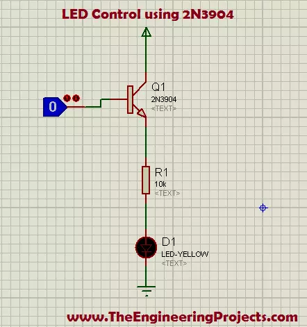
- As there's no voltage applied at Base Terminal, so 2N3904 is reverse biased and thus LED is OFF.
- Now when we have applied 5V at Base Terminal(using LogicState in Proteus), 2N3904 gets forward biased and now LED is ON, as shown in below figure:
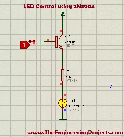
- So, that's how we can use 2N3904 transistor as a switch.
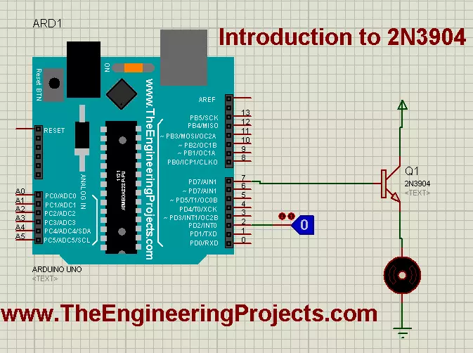
2N3904 Arduino Interfacing in Proteus
- I have made another simulation in Proteus ISIS for DC motor control using 2N3904.
- The screenshot of the simulation is shown in the figure below.
- The complete Arduino source code of the above simulation is given below.
- You have to get the hex file in Arduino to observe the results properly.
int MotorInput = 2;
int MotorOutput = 7;

void setup()
{
    pinMode(MotorInput, INPUT_PULLUP);
    pinMode(MotorOutput , OUTPUT);
}

void loop()
{
    if(digitalRead(MotorInput) == HIGH)
    {
      digitalWrite(MotorOutput, HIGH);
    }
    if(digitalRead(MotorInput) == LOW)
    {
      digitalWrite(MotorOutput, LOW);
    }

}
- The running form of the above simulation is shown in the below figure:

- From the above figure you can see that after uploading .hex file and running the simulation you need to change the level of logic state from 0 to 1, and the motor will start to rotate.
- You can download the complete Proteus ISIS simulation as well as complete Arduino source code, here by clicking on the button below.
- Just download .rar file, extract it and enjoy the complete package.
- You should watch this below video to understand how to run this Proteus Simulation:
×
![]()