Energy, is a small word, but is the problem of whole world. Particularly when we are talking about electrical energy. IF you consume more electrical energy then you will get quite huge bill at the end of the month. :P So, there's always work done on reducing the consumption of electrical energy and also we compare energy costs from different providers. As a human, suppose you turn ON your room fan, then normally you forget to turn it OFF and thus your bill keeps on increasing. So in order to avoid this, automation is the only tool which comes in handy. Like there must be such system which automatically detects whether someone is still in the room or not and if there's no one then lights got OFF automatically. In this way, you can quite easily reduce your electricity cost. This same concept is presented in this project, let's have a complete look over it. :)
Overview of Intelligent Energy Saving System
- In this project, we have designed a complete room and used two inductive loads i.e. bulbs and one fan.
- Now the purpose of this project was to save the energy so we used two IR sensors for counting.
- Now, if there's no one present in the room then the loads will automatically turn OFF and when someone will enter in the room then the loads will automatically turn ON.
- Moreover, we have also added a counter functionality in it i.e. the project will also count the number of people present in the room.
- All these parameters will also display on the LCD attached with Arduino.
Components Used
I am mentioning here the components used in designing this project. I am not giving the exact values as you will get them in the circuit diagrams. Here's the list:
- Arduino UNO
- IR Sensors
- 16 x 2 LCD
- 100W Bulbs
- 12V Fan
- 2 Relay Board
- 7805 (IC Regulator)
- LED (Indication)
- Resistance
- Capacitors
Circuit Diagrams of Intelligent Energy Saving System
Suppose you are designing this project then the first thing you are gonna need is the circuit diagrams for the project so here I am gonna show you all the circuit diagrams step by step so let's start:
1: Interfacing of Arduino with LCD
- First thing we are gonna need is the interfacing of Arduino with LCD. LCD used in this project is 16 x 2.
- I have first designed the simulation in Proteus as its always better to design the simulation before going into real hardware.
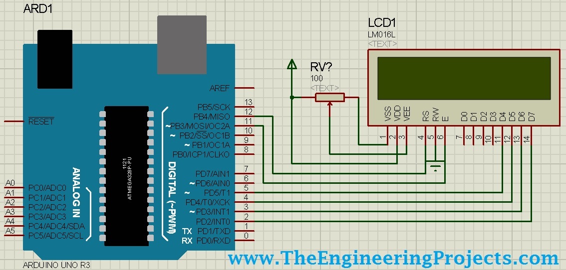
- Now upload the below code into it, just to test that whether its working fine or not:
    #include <LiquidCrystal.h>
    LiquidCrystal lcd(12, 11, 5, 4, 3, 2);

    void setup()
    {

    lcd.begin(16, 2);
    lcd.print("www.TheEngineer");
    lcd.setCursor(0,1);
    lcd.print("ingProjects.com");
    }
    void loop() {}
- Now run it and if everything's gone fine then you will get something as shown in below figure:
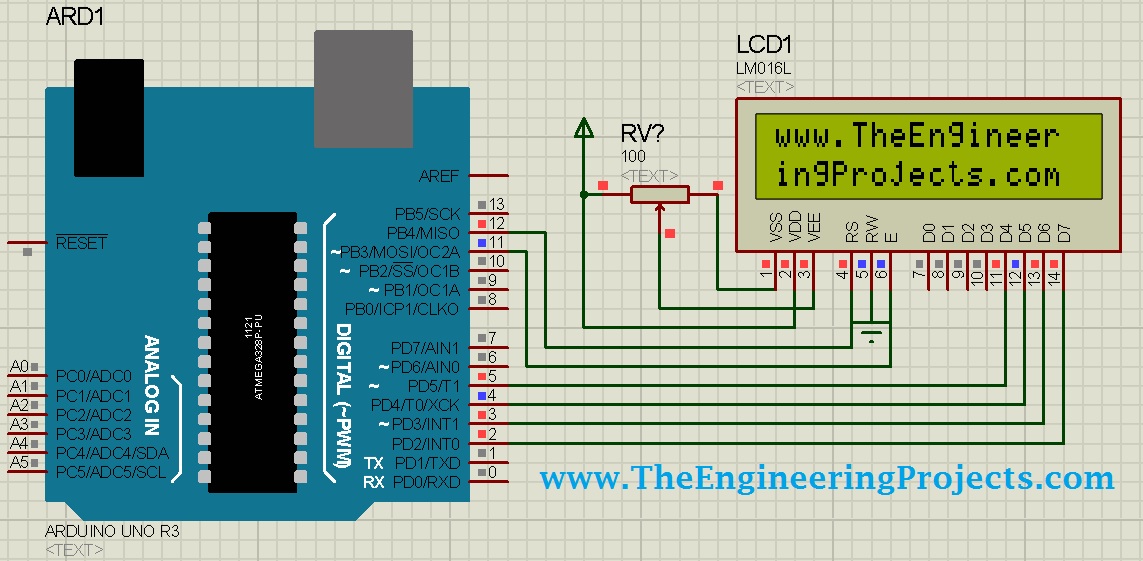
- If you are new to LCD then you can read more about it in Circuit Designing of LCD with Arduino in Proteus ISIS.
- You should also read Arduino Library for Proteus so that you can use Arduino in Proteus.
2: Circuit diagram of 2 Relay Board
- Next thing we are gonna need is the two relay board. Using these relays we are gonna turn ON or OFF our loads.
- Here's the circuit diagram for 2 relay board.
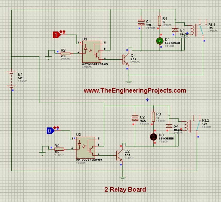
- As you can see in the above figure, I have used two relay board, where both the relays are controlled bt simple logic operators.
- Now instead of these logic operators, you need to give Arduino Pins here.
- I have made the first relay ON while the second relay is OFF.
- In the above figure, relay outputs are open so you can place anything here as its gonna act as switch. So, in our case the loads will be placed after this relay.
3: Circuit Design of Buzzer
- Next circuit design which we need to understand is the buzzer circuit design.
- Its quite simple and similar to 2 relay board. I have also published a detailed post on How to Design a Buzzer in Proteus ISIS, which will be quite helpful.
- Here' I am gonna explain it lightly, so let's have a look at the circuit diagram of buzzer:

- You can quite easily understand the above figure, where I have shown both the ON and OFF states of buzzer.
4: Circuit Diagram of IR Sensor:
- In this project, I have used two IR sensors, both are placed on the door one after another. You can read more about the designing of IR Sensor on my post Circuit Diagram of IR Sensor using 555 Timer.
- I have named them Entering IR Sensor and Leaving IR Sensor.
- The logic behind these two sensors is that, when someone enters in the room then he will first pass the Entering IR Sensor and then will hit the Leaving IR Sensor and if someone is leaving the room then he will first pass the Leaving IR Sensor and then will cut the Entering.
- So, in this way I am counting the persons if someone entering in the room I simply increment and if someone's leaving then I decrement.
- Now, if number of people in the room becomes zero then I turn OFF all the lights and the fan, and if there even one person in the room then I turn ON the lights and fan.
- Here's the circuit diagram of IR Sensor:
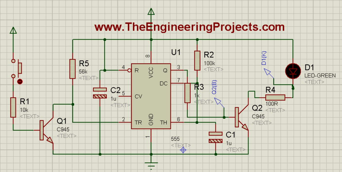
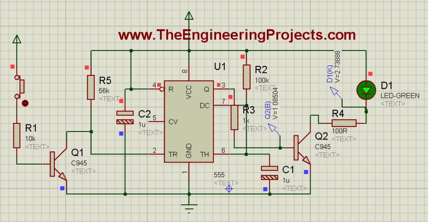
- IR transmitter and Receiver are not available in Proteus so that's why I have used the button so when you press the button, its like someone cut the beam of IR sensor, and you will get below result:
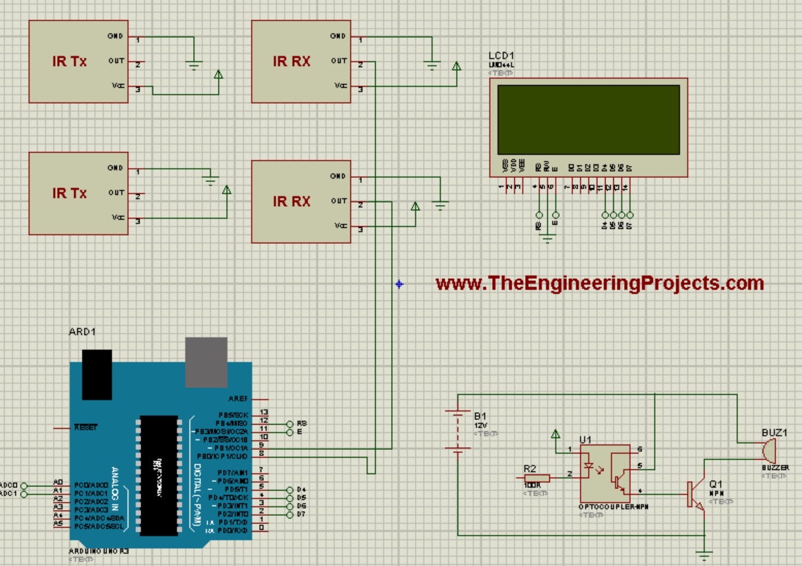
5: Complete Circuit Diagram of Intelligent Energy Saving System
- Now that we have designed the individual circuit diagrams, next thing we are gonna do is the assembly of complete project.
- So, here's the complete circuit diagram of this project:

- As you can see in the above figure, I have used two IR Sensors. The first IR Sensor is for entering in the room while the IR sensor is for leaving the room.
- Next is the buzzer circuit which is also quite simple and I have explain in detail above.
- LCD will display the no of people in a room and will also display either the bulb is ON or OFF, and also about Fan status.
- I haven't shown the relay circuit in above figure as it will not fit in the space and I think you guys can place it easily.
Programming Code for Intelligent Energy Saving System
- The code designed for this project is developed in Arduino software.
- Code is as follows:
#include <LiquidCrystal.h>
#include <OneWire.h>
#include <DallasTemperature.h>

#define ONE_WIRE_BUS 8
OneWire oneWire(ONE_WIRE_BUS);
DallasTemperature sensors(&oneWire);
LiquidCrystal lcd(12, 11, 5, 4, 3, 2);

float celsius, fahrenheit;

int Sensor1 = A0;
int Sensor2 = A1;

int Bulb = A5;
int Fan = A4;
int Buzzer = A3;

int Counter = 0;
int Sen1Check = 0;
int Sen2Check = 0;

void setup(void)
{
    Serial.begin(9600);
    digitalWrite(Bulb, HIGH);
    digitalWrite(Fan, HIGH);
    digitalWrite(Buzzer, HIGH);
    pinMode(Sensor1, INPUT);
    pinMode(Sensor2, INPUT);
    pinMode(Bulb, OUTPUT);
    pinMode(Fan, OUTPUT);
    pinMode(Buzzer, OUTPUT);


    lcd.begin(20, 4);
    lcd.setCursor(0, 1);
    lcd.print("Temp = ");
    lcd.setCursor(0, 0);
    lcd.print("Counter = ");
    lcd.setCursor(12, 0);
    lcd.print("Persons");
}

void loop()
{
  CheckEntry();
  CheckLeaving();
  lcd.setCursor(7, 1);
  sensors.requestTemperatures();
  lcd.println(sensors.getTempCByIndex(0));
  lcd.setCursor(12, 1);
  lcd.print(" degC");
  lcd.setCursor(10, 0);
  if(Counter >= 0){lcd.print(Counter);}
  if(Counter < 0){Counter = 0;}

  if(Counter > 0)
  {
      digitalWrite(Bulb, LOW);
      digitalWrite(Fan, LOW);
      digitalWrite(Buzzer, HIGH);
      lcd.setCursor(0, 2);
      lcd.print("Fan : ON ");
      lcd.setCursor(0, 3);
      lcd.print("Bulb : ON ");
  }

  if(Counter < 1)
  {
      digitalWrite(Bulb, HIGH);
      digitalWrite(Fan, HIGH);
      digitalWrite(Buzzer, HIGH);
      lcd.setCursor(0, 2);
      lcd.print("Fan : OFF");
      lcd.setCursor(0, 3);
      lcd.print("Bulb : OFF");

  }


}


void CheckEntry()
{
    if(((digitalRead(Sensor1) == LOW) || (Sen1Check == 1)) && (Sen2Check == 0))
    {
        while(digitalRead(Sensor1) == LOW);
        Sen1Check = 1;

        if(digitalRead(Sensor2) == LOW)
        {
            Counter++;
            Sen1Check = 0;
            while(digitalRead(Sensor2) == LOW);
        }
    }
}


void CheckLeaving()
{
    if(((digitalRead(Sensor2) == LOW) || (Sen2Check == 1)) && (Sen1Check == 0))
    {
        while(digitalRead(Sensor2) == LOW);
        Sen2Check = 1;

        if(digitalRead(Sensor1) == LOW)
        {
            Counter = Counter - 1;
            Sen2Check = 0;
            while(digitalRead(Sensor1) == LOW);
        }
    }
}
- Coding isn't much difficult for this project, but still if you get into some trouble ask in comments and I will check it out.
- Here's the complete video for this Intelligent Energy Saving System, which will explain all about the project.


