As 8051 Microcontroller is concerned, we all know that Its a Microcontroller in which we program our code and make it work. The 8051 microcontroller, I have used in this post is AT89C51. I have also designed this project on hardware and have tested code and it works fine. The crystal oscillator I have used in this project is of 16MHz. You can also download the Proteus Simulation along with programming code and hex file designed in keil uvision 3, at the end of this post. So, now let's get started with it. You may also wanna read the below projects on 8051 Microcontroller:
- Interfacing of LCD with 8051 Microcontroller
- Interfacing of Keypad with 8051 Microcontroller
- Design a simple Calculator with 8051 Microcontroller
Interfacing of Seven Segment Display with 8051 Microcontroller
- Seven Segment Display is of two types which is common cathode and common anode.
- In this post, I have used common anode but you can easily use this code for common cathode but you have to do small change in the hardware.
- If you are using common cathode then instead of GND you have to give +5V to the Seven Segment Display.
- So, now let's first design the Proteus Simulation of Seven Segment Display with 8051 Microcontroller.
Proteus Simulation
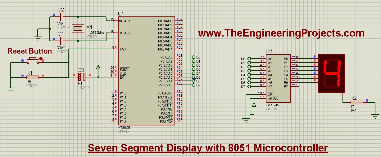
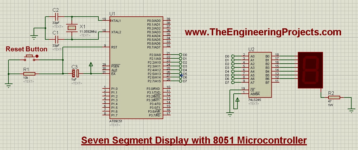
- First of all, design a Proteus Simulation for Interfacing of Seven Segment Display with 8051 Microcontroller,as shown in below figure:

- Now you can see in the above figure that I have used 8051 Microcontroller which is AT89C51.
- I have used Seven Segment display which is of Red color.
- It has total 8 pins so we have connected these 8 pins of Seven Segment Display to 8 pins of Port 2 of 8051 Microcontroller.
- Now, the last thing, I have used is 74LS245. Its kind of a current amplifier. 8051 Microcontroller provides quite small current on its output pins which is not quite enough for the Seven Segment Display to turn its LEDs ON.
- So, we used this 74LS245 which provides extra current and makes the Seven Segment Display to work properly.
- Now, let's design the programming code for this project.
Programming Code
- I have designed the programming code for interfacing of Seven Segment Display with 8051 Microcontroller in Keil uvision 3 compiler.
- The programming code is as follows:
#include<reg51.h>

void cct_init(void);
void delay(int);
void DisplayOn7Segment(char);

int main(void)
{
   char ch = '0';	          // Character to be displayed on 7seg

   cct_init();   	          // Make all ports zero

   while(1)
   {
	DisplayOn7Segment(ch);	  // Display ch on 7seg
	delay(30000);			  // About 1 sec delay

	switch(ch)				  // Update ch with new value to be displayed
	{
		case '0':	ch = '1';  break;
		case '1':	ch = '2';  break;
		case '2':	ch = '3';  break;
		case '3':	ch = '4';  break;
		case '4':	ch = '5';  break;
		case '5':	ch = '6';  break;
		case '6':	ch = '7';  break;
		case '7':	ch = '8';  break;
		case '8':	ch = '9';  break;
		case '9':	ch = '0';  break;


		default: ch = '0';  break;
	}
   }
}

void cct_init(void)
{
	P0 = 0x00;
	P1 = 0x00;
	P2 = 0x00;
	P3 = 0x00;
}

void delay(int a)
{
   int i;
   for(i=0;i<a;i++);   //null statement
}

void DisplayOn7Segment(char ch)   // ch can have a value from '0' to 'F' only
{
	switch(ch)
	{
		case '0':	P2 = 0x3F;  break;
		case '1':	P2 = 0x06;  break;
		case '2':	P2 = 0x5B;  break;
		case '3':	P2 = 0x4F;  break;
		case '4':	P2 = 0x66;  break;
		case '5':	P2 = 0x6D;  break;
		case '6':	P2 = 0x7D;  break;
		case '7':	P2 = 0x07;  break;
		case '8':	P2 = 0x7F;  break;
		case '9':	P2 = 0x6F;  break;


		default: P2 = 0x3F;  break;
	}
}
- Now the code code is quite simple. I have added a small delay of 1 second and then displayed the character and stored the next character in array.
- So, in this way we are displaying the characters from 0 to 9 and then repeats the process.
- Now, you have seen the basics of Seven Segment Display with 8051 Microcontroller and now you can design any kind of project on it, like you can create a counter or a timer.
- Now, compile the code and get the hex file and upload it to your 8051 Microcontroller and run the simulation.
- If everything goes fine then you will get the results as shown in below figure:

- You can download the Programming code and Simulation for interfacing of Seven Segment Display with 8051 Microcontroller, by clicking on the below button.
That's all for today, I hope now you can quite easily interface this seven segment display with 8051 Microcontroller. In the next post, we will have a look at some new project with 8051 Microcontroller. So, till then take care and have fun !!! :)


