Arduino has 10 bit ADC pins so whenever you apply voltage on these pins it will give you a value ranging from 0 to 1023 depending on the voltage provided. One can easily get this value using a simple function in Arduino analogRead(); but the real problem is to convert this analog value into the actual voltage present on the pin. Suppose you are using A0 pin of arduino and you are providing 3.3V over to this pin, now when you use this analoagRead() function then it will give you some value say 543, but you wanna know what's the actual voltage at this pin which is 3.3V so now converting this 543 to 3.3 is a bit tricky part. It's not difficult but involves a little calculations, which I am gonna cover today in detail. Before going any further, make sure you have already installed the Arduino Library For Proteus, if not then first do it because without this library you won't be able to use Arduino board in Proteus. So, let's get started with How to Display ADC value on LCD using Arduino.
Display ADC value on LCD using Arduino in Proteus ISIS
I have divided this tutorial on How to Display ADC value on LCD using Arduino in few steps, follow these steps carefully and if you get into some trouble then ask in comments and I will try my best to resolve them, all the materials are provided at the end of step 1 for download but I suggest that you design your own so that you do mistakes and learn from them. Moreover, you should also have a look at these Arduino Projects for Beginners. Anyways, let get started:
Step1: Circuit Designing in Proteus
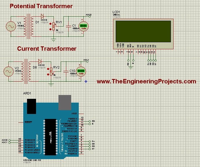
- First of all, I have designed a circuit in Proteus for Displaying ADC value on LCD using Arduino.
- In this circuit, I have used two transformers which I have named as Potential Transformer and Current Transformer. I am supplying 220V to these transformers which is then converted into 5V.
- I have set the turn ratio of these transformers such that they give maximum 5V at the output.
- Now,rest of the circuit is simple, I have just connected the LCD with Arduino so that we could display these ADC value over to LCD.
- Before connecting any pin to ADC, make sure that the output should be less than 5V. Otherwise, there's a chance that the pin burnt out.
- If you don't know about LCD then read Ciruit Designing of LCD with Arduino in Proteus.
- You should also download this New LCD Library for Proteus.
- Here's the circuit diagram of displaying ADC value on LCD using Arduino in Proteus ISIS:

- You can download the Proteus Simulation and the Arduino hex file for Displaying ADC value on LCD using Arduino by clicking on below button:
Download Proteus Simulation and Arduino Hex File
- It's quite simple and self explanatory. After designing the circuit diagram, now let's move to second step, which is code designing for Displaying ADC value on LCD using Arduino.
Step 2: Arduino Code Designing
- Now copy the below code and paste it into Arduino software. Compile your code and get the Arduino hex file.
- If you dont know How to get the hex file from Arduino then read Arduino Library for Proteus, I have explained it in detail there.
#include <LiquidCrystal.h>
#define NUM_SAMPLES 10

int sum = 0;
unsigned char sample_count = 0;
float voltage = 0.0;

LiquidCrystal lcd(12, 11, 5, 4, 3, 2);
const int PT = A0;
const int CT = A1;
float Cur;
float Vol;
float Power;

void setup() {
// set up the LCD's number of columns and rows:
lcd.begin(20, 4);
// Print a message to the LCD.
lcd.setCursor(6,1);
lcd.print("Welcome To");
lcd.setCursor(5,2);
lcd.print("Energy Meter");
//delay(5000);
lcd.clear();

Constants();
}

void loop() {
lcd.setCursor(0, 2);
ShowVoltage(9, 0, PT);
Vol = voltage;
ShowVoltage(9, 1, CT);
Cur = voltage;
Power = Vol * Cur;
lcd.setCursor(7,2);
lcd.print(Power);
}

void Constants()
{
lcd.setCursor(0,0);
lcd.print("Voltage: ");
lcd.setCursor(0,1);
lcd.print("Current: ");
lcd.setCursor(0,2);
lcd.print("Power: ");
lcd.setCursor(14,0);
lcd.print("V");
lcd.setCursor(14,1);
lcd.print("A");
lcd.setCursor(12,2);
lcd.print("W");
}

void ShowVoltage (int x,int y, unsigned int value)
{
while (sample_count < NUM_SAMPLES)
{
sum += analogRead(value);
sample_count++;
delay(10);
}

voltage = ((float)sum / (float)NUM_SAMPLES * 5.015) / 1024.0;
lcd.setCursor(x, y);
lcd.print(voltage);
sample_count = 0;
sum = 0;
}
- The code is quite simple and self explanatory, the only difficulty is in ShowVoltage function. In this function, I have first taken an average of 10 ADC values and after that I have applied a simple formula over it and then it will start start giving the voltage value which I have simply displayed over the LCD.
- Now everything's done, so Get your Hex File from Arduino Software and let's check the results whether it displayed ADC value on LCD using Arduino or not
Step 3: Result
- We have designed the electronic circuit in Proteus and have also designed our code and uploaded the hex file in Arduino.
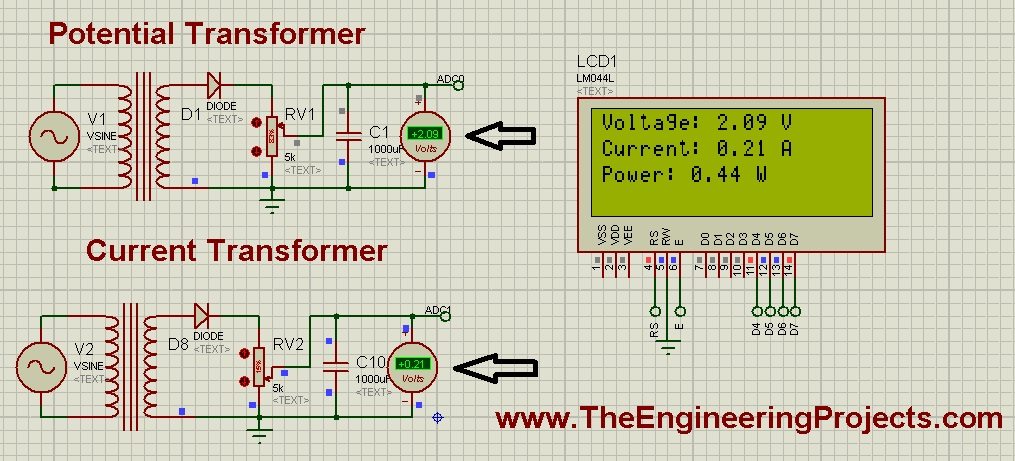
- Now press start button and you will see something like this:

- Now if you compare the voltages in voltmeter and on LCD, you can see they are exactly the same. You can check the value of variable resistor and the values in LCD will also change as the voltage in voltmeter change.


