Servo motor is a DC operated motor and it is available in various sizes and powers. Generally the servo motor used in basic projects, is named as micro servo motor. It is of small size and low power rating. But as I stated earlier that it needs dc supply to operate but it also needs a continuous pulse train to operate and this pulse is commonly generated by some sort of timers or micro controllers. Since my today’s project tutorial (Angle Control of Servo Motor using 555 Timer in Proteus ISIS) is of basic level so, we will be using 555 timer to generate the continuous pulse train or PWM. Now let’s move towards hardware but dear friends, always remember that to become a technical person, you must have to perform technical work by yourself.
Angle Control of Servo Motor using 555 Timer in Proteus ISIS
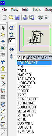
- First of all, place the components in your Proteus workspace, as shown below in image.

-
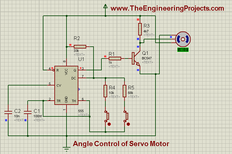
A 555 timer is an 8 pin IC. Pin # 6 is called threshold pin and for 555 timer threshold level is 5 volts.
- So, 555 timer will trigger above 5 volts and it will generate output which can be collected from pin # 3 represented as ‘Q’ which is output pin of 555 timer.
- After that the output pulse is sent to servo motor through a Transistor which is BC547.
- BC547 is basically a NPN transistor and the pulse signal is sent to servo motor through its Emitter.
- The full angle deflection of servo motor is from -180 degrees to +180 degrees. It can’t rotate through full 360 degrees. Now it’s your own choice that either you want to rotate the motor at one particular angle or at multiple angles or to get full rotation.
-
Since in this tutorial (Angle Control of Servo Motor using 555 Timer), we are going to get full deflection of motor so, we have inserted 2 switches in the circuit. The complete circuit will look like:

-
Switch # 1 will rotate the servo motor to 180 degrees in anti-clockwise direction. We will press the button only once and when the motor completes its rotation, it will automatically stop.
- After that if we press the switch # 2, then it will rotate the servo motor in clockwise direction and again after completing the angle, motor will again stop.
-
If you have connected the components in correct order and when you will run it, the exact simulation will look like as shown:

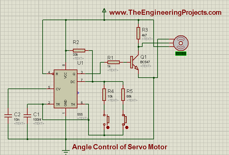
- Sonow, if you have a close look on the above two iages then you can see in theState # 1 image I have pressed the left button and the servo motor is moved to -90 degree, this -90 is also mentioned in the green LEDbox just below servo motor.
- And in State # 2, I have pressed the right button and thus the motor is moved to +90 degrees. That's how it will work.
- You can Download the simulation of Angle Control of Servo Motor Project Using 555 Timer in Proteus ISIS, by clicking on below button:
Download Angle Control of Servo Motor Project using 555 Timer
Alright Friends, that's all for today, In the coming posts, we will discuss few more such projects. Till than, take care and be safe !!! :)


