TEP , The Engineering Projects , Author Welcome! Syed Zain Nasir Mechatronics Engineer TEP , The ENgineering Projects , TEP Badge TEP , The Engineering Projects , Ratting Background 7.5 7.5/10
TEP , The Engineering Projects , Rating Percentage Background Reputation Score 55 / 100
Introduction to PLC, Fatek PLC Introduction, Getting Started With PLC, Getting Started With Fatek PLC
TEP , The Engineering Projects , Boxes

Logical Gates in Ladder Logic for PLC

TEP , THe Engineering Projects , Shares 2.5K Views
TEP , The ENgineering Projects , Reaction 40
TEP , The ENgineering Projects , Reaction 700
TEP , The ENgineering Projects , Reaction 60
TEP , The ENgineering Projects , Reaction 25
TEP , The ENgineering Projects , Reaction 60
TEP , The Engineering Projects , Pintrest TEP , The Engineering Projects , Pintrest TEP , The Engineering Projects , Pintrest TEP , The Engineering Projects , Pintrest TEP , The Engineering Projects , Pintrest
Shares: 691
TEP , The Engineering Projects , PCBWAY

Introduction to PLC, Fatek PLC Introduction, Getting Started With PLC, Getting Started With Fatek PLC
In the previous post Logical Gates in Ladder Logic for PLC, we had an overview of what is Ladder Logic programming and we have also implemented three basic Logical gates in Ladder Logic form. Today, we are gonna have a look at some complex Logical Gates in Ladder Logic for PLC. So, I hope till now you guys have basic knowledge of Ladder Logic and can implement complex logical gates in it. If you haven't read the previous post then must read because without that knowledge you won't understand this post.

In today's post we are gonna implement few complex logical gates. Its not gonna be much difficult if you have the basic concepts. I am just pointing out few important points here. While implementing any gate in ladder logic, always consider rung as an electrical line having HIGH voltage at one end and LOW voltage at the other, while the inputs are simple switches. Voltage will be supplied to the output only when switch is closed i.e. input is HIGH, otherwise the output will remain OFF. You should also have a look at Introduction to Logic Gates.

You have seen in previous post, while implementing OR gate we have used a second switch in parallel which ends at the first rung so overall its a single rung having two inputs in parallel so input can come either from first switch or from second one. So, now let's start implementing some complex logical gates in Ladder Logic for PLC. Today, we are gonna implement these logic gates:

  • NAND Logical gate in Ladder Logic for PLC
  • NOR Logical gate in Ladder Logic for PLC
  • XOR Logical gate in Ladder Logic for PLC
  • XNOR Logical gate in Ladder Logic for PLC

NAND Logical gate in Ladder Logic for PLC

  • NAND gate is another type of logical gate, which is normally used. NAND gate is nothing but a simple NOT of AND gate. In simple words, if we add a NOT gate in front of AND gate, we get NAND gate. The truth tablel of NAND gate is shown in the below figure:
implement logical gates in PLC, logical gates in ladderlogic diagram, logical gates in PLC, truth table of nand gate
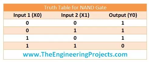
  • It is quite obvious from the truth table of NAND gate that the output will be OFF only when both the inputs will be ON otherwise output will remain ON. So, now lets implement this gate in ladder logic programming.
  • The below image shows the implementation of NAND logical gate in Ladder Logic form:
implement logical gates in PLC, logical gates in ladderlogic diagram, logical gates in PLC, truth table of nand gate
  • Now, if you understand the above figure, then its quite obvious. We have used both inputs in normally closed form so when both inputs are OFF the output will be ON. If we get X0 ON then in still we will get the HIGH voltage from X1. If we make X1 ON then we get HIGH voltage from X0, but if we get both X0 and X1 ON then our Y0 will get OFF. Again we are using inputs in normally closed form so when our actual input is OFF then our X0 is closed. :)

NOR Logical gate in Ladder Logic for PLC

  • In NOR gate, we simple place a NOT gate in front of OR gate. Its truth table is shown in below figure:
implement logical gates in PLC, logical gates in ladderlogic diagram, logical gates in PLC, truth table of nand gate
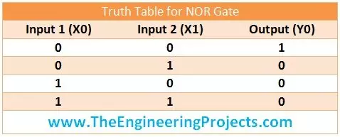
  • From the truth taable of NOR gate, its quite obvious that its output will be ON when both of its input goes OFF otherwise the output will remain ON. Lets implement this NOR logical gate in Ladder Logic diagram.
  • The below figure shows the NOR logical gate in ladder logic diagram:
implement logical gates in PLC, logical gates in ladderlogic diagram, logical gates in PLC, truth table of nand gate
  • If you got the ladder logic form of NAND gate, then its not gonna be much problem. Simple two normally closed inputs are placed in series, so now when any of them gets ON, then output will get OFF.
Note:
  • If you have noticed, whenever NOT gate is involved somewhere, we use normally closed inputs.

XOR Logical gate in Ladder Logic for PLC

  • The truth table of XOR gate is shown in below figure:
implement logical gates in PLC, logical gates in ladderlogic diagram, logical gates in PLC, truth table of xor gate
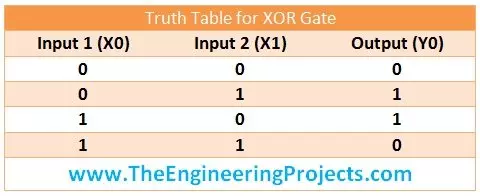
  • From the truth table, we can get this thing that, output will ON only when the inputs are in opposite states and output will be OFF when inputs are in same state.
  • The ladder logic implementation of XOR gate is shown in below figure:
implement logical gates in PLC, logical gates in ladderlogic diagram, logical gates in PLC, truth table of xor gate
  • Now it has gone a little complex but lets understand how's its working. We have placed X0 and X1 in series and also in parallel, but in first string X0 is normally open and X1 is normally closed while in second string X0 is normally closed and X1 is normally open.
  • Now, what we need to do is if both inputs are in same state we need to turn OFF the output. That's what we are doing in above logic diagram. Let's say X0 and X1 both are OFF then the normally open switches will be OFF and they wont let the HIGH voltage pass and hence our Y0 will remain OFF. And if both are ON then the normally closed will be OFF and again Y0 will remain OFF.
  • Now if X0 is ON and X1 is OFF, then the first string will connect and our output will ON, and if X0 is OFF while X1 is ON then our second string will connect and will make our output ON. Quite simple and easy.

XNOR Logical gate in Ladder Logic for PLC

  • Last but not the least XNOR gate, if we add NOT gate in front of XOR gate we get XNOR gate, let's have a look at its truth table below:
implement logical gates in PLC, logical gates in ladderlogic diagram, logical gates in PLC, truth table of xor gate
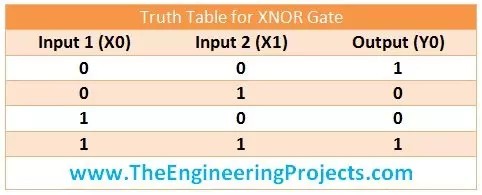
  • So, in XNOR gate, we get our output ON when both inputs are in same state otherwise its OFF. Let's implement it in ladder logic form below:
Logical Gates in Ladder Logic for PLC
  • Now in this ladder logic diagram, we are getting introduced with a new symbol, till now we have used normally open output but here for the first time, we are using normally closed output Y0.
  • It's exactly the same logic as we used for XOR gate, but the only difference is ere we are using normally closed output. So, simple when the output is gets ON, its actually OFF and when it gets OFF its actually ON ;)
  • I hope now you got the clear concept of How to do programming using Ladder Logic and what's its difference with Microcontrollers like Arduino or PIC Microcontroller etc.
That's all for today, hope I have conveyed some knowledge. If you are new to PLC programming then you won't get it in the first attempt so my suggestion is give it some time, read it again and again and you will feel better :) I am not gonna post more about Ladder Logic designing, instead in the next post we are gonna have n overview of PLC simulation software in which we design this ladder logic diagrams. Till then take care and have fun :)
TEP , The Engineering Projects , Tags
Introduction to PLC
Fatek PLC Introduction
Getting Started With PLC
Getting Started With Fatek PLC
TEP , The Engineering Projects , Comments

Write a Comment

TEP , The Engineering Projects , WordPress TEP , The Engineering Projects , Google TEP , The Engineering Projects , Twitter TEP , The Engineering Projects , Facebook TEP , The Engineering Projects , User
TEP , The Engineering Projects , Robot
TEP , The Engineering Projects , Comments Comments on ‘’ Logical Gates in Ladder Logic for PLC ‘’ (6)
TEP , The Engineering Projects , Comment
TEP , The ENgineering Projects , Reaction 40
TEP , The ENgineering Projects , Reaction 700
TEP , The ENgineering Projects , Reaction 60
TEP , The ENgineering Projects , Reaction 25
TEP , The ENgineering Projects , Reaction 60
Hi, Rite now I'm more concerned about the basic concepts, so I won't recommend any simulation software instead I'll more focus on developing logics which I'm gonna cover in future articles, will also post about simulation software for plc. Thanks.
TEP , The Engineering Projects , About TEP , The Engineering Projects , About Shadow

Top PCB Design Service

PCBA
TEP , The Engineering Projects , JLCPCB
PCB
TEP , The Engineering Projects , JLCPCB
TEP , The Engineering Projects , About TEP , The Engineering Projects , About Shadow

Embedded Tools

ARDINO TEP , The Engineering Projects , JLCPCB
TEP , The Engineering Projects , About TEP , The Engineering Projects , About Shadow

Subscribe Now !!!

Learn Free Pro Tricks

TEP , The Engineering Projects , Mail Receive Quality Tutorials Straight in your Inbox by Submitting your Email ID Below
TEP , The Engineering Projects , Mail TEP , The Engineering Projects , Mail Shadow
TEP , The Engineering Projects , Mail Robot TEP , The Engineering Projects , Mail Robot Shadow TEP , The Engineering Projects , Mail Robot Shadow
TEP , The Engineering Projects , About TEP , The Engineering Projects , About Shadow

Engineering Books

TEP , The Engineering Projects , Arduino Programming Book
SALE $20
Text Book for arduino $20
TEP , The Engineering Projects , Rating Stars (5.0)
TEP , The Engineering Projects , Arduino Programming Book
SALE $20
Text Book for Raspberry Pi $20
TEP , The Engineering Projects , Rating Stars (3.0)
TEP , The Engineering Projects , Arduino Programming Book
SALE $20
Text Book for arduino $20
TEP , The Engineering Projects , Rating Stars (4.7)
TEP , The Engineering Projects , Arduino Programming Book
SALE $20
Text Book for Raspberry Pi $20
TEP , The Engineering Projects , Rating Stars (5.0)
TEP , The Engineering Projects , TEP Robot TEP , The Engineering Projects , TEP Robot Shadow TEP , The Engineering Projects , TEP Robot Shadow
TEP , The Engineering Projects , About TEP , The Engineering Projects , About Shadow

Categories

TEP , The Engineering Projects , Arduino
TEP , The Engineering Projects , Notification 20K
TEP , The Engineering Projects , Tick 900
TEP , The Engineering Projects , Views 900
TEP , The Engineering Projects , Comments 20K
TEP , The Engineering Projects , Arduino
TEP , The Engineering Projects , Notification 20K
TEP , The Engineering Projects , Tick 900
TEP , The Engineering Projects , Views 900
TEP , The Engineering Projects , Comments 20K
TEP , The Engineering Projects , Arduino
TEP , The Engineering Projects , Notification 20K
TEP , The Engineering Projects , Tick 900
TEP , The Engineering Projects , Views 900
TEP , The Engineering Projects , Comments 20K
TEP , The Engineering Projects , Arduino
TEP , The Engineering Projects , Notification 20K
TEP , The Engineering Projects , Tick 900
TEP , The Engineering Projects , Views 900
TEP , The Engineering Projects , Comments 20K
TEP , The Engineering Projects , Arduino
TEP , The Engineering Projects , Notification 20K
TEP , The Engineering Projects , Tick 900
TEP , The Engineering Projects , Views 900
TEP , The Engineering Projects , Comments 20K