Hello everyone! I hope you will be fine and having fun. Today, I am going to give a detailed Introduction to Relay. In this tutorial, we will learn the basics of relays, the working principle of relays, the types of relays and their applications in detail.
A relay is a simple automatic switch that opens and closes the circuit(either electronically or mechanically) based on its input signal. A relay is an electromechanical switch that uses electromagnetism from a small current or voltage to switch higher current or voltage for different appliances. When a relay is in a Normally Open (NO) state, no current passes through it and when the relay is energized, the current starts to flow and we can say the relay is in a Normally Closed state. You should also have a look at Relay Interfacing with Microcontroller using ULN2003.
A Relay is used to control high-power devices with small current devices i.e. microcontrollers. When a small voltage is applied(normally from microcontrollers) to the input coil of a relay, it gets energized and the relay output changes its position from NO to NC. Relays are also used for protection purposes i.e. overload, reverse, under current, over current etc.
Now let's have a detailed overview of What is Relay???
What is a Relay?
Relay is an automatic switch, which opens and closes the circuit electronically. It uses electromagnetism from small voltage to provide higher voltages. It has two basic contacts i.e. NO (Normally Open) and NC (Normally Closed). When input voltage is applied across its coil, NC changes to NO and NO changes to NC. When input voltage is supplied, we say that the relay is energized. It has several features e.g. it can be used for switching smaller voltage to higher. But it can not be used in power-consuming devices. It has a wide range of applications. It can be used in home appliances, electronic circuits where there is a need of protection, robotics for controlling its motors for the proper motion and many more. A basic relay is given in the figure shown below.
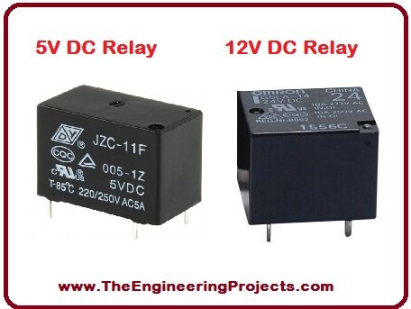
1. Relay Pins
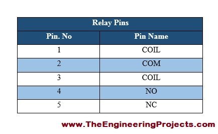
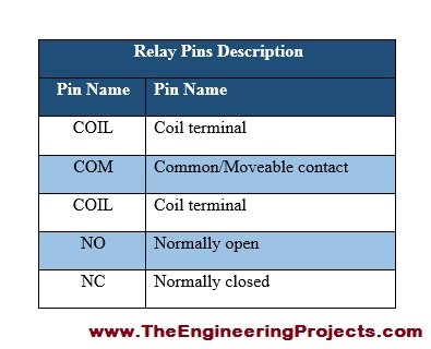
- Relay has total five (5) pins with different individual functions.
- Three pins are at one side of the structure.
- The other two pins are on the opposite side of the structure.
- All of these pins are provided in the table given in the figure shown below.
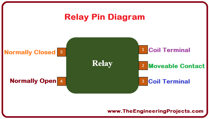
- I have also made a relay pin configuration diagram.
- Pin configuration diagram is shown in the figure given below.
2. Relay Pins Description
- Each pin has different functions to perform.
- So, we must know about each of the function before using it, for the better use of it.
- All these pin descriptions are listed in the table shown in the figure below.
3. Relay Internal Structure
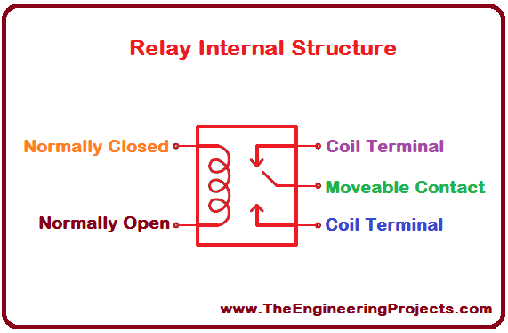
- Internal structure of any electronic device leads to the better understanding about its working principle.
- I have made a completely labeled internal structure of relay along with its pin configurations.
- Relay internal structure is shown in the figure given below.
4. Relay Pinout
- If you want to know about the pin configuration of any electronic device you must have a look at its pinout diagram.
- Pinout diagram helps us to understand the pin configurations in a better way.
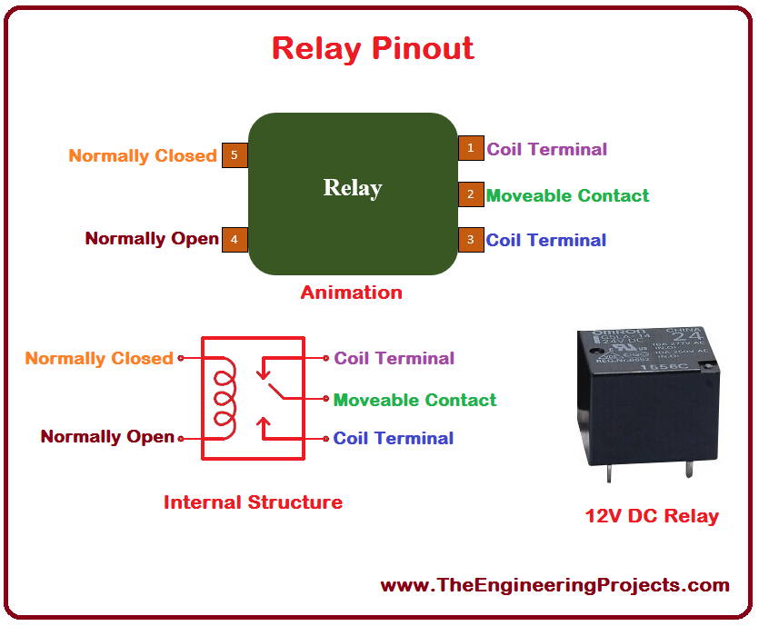
- I have made a pinout diagram which contains relay animation, internal structure and the real image.
- Relay pinout diagram is given in the figure shown below.

5. Relay Working Principle
- Relay works on a pretty simple principle.
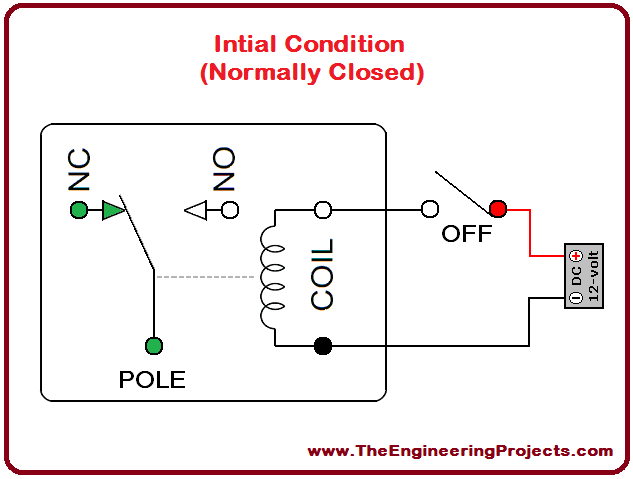
- Initially when the power is not supplied and relay is in normally open condition, its contact will be opened.
- When relay is in normally closed condition, its contact will be closed.
- When power is supplied to its coil, it gets energized and its normally open condition is changed to normally closed and normally closed condition is changed to normally open.
- If we want to control the device via relay through a software then we have to attach this device to its normally open terminal.
- When the relay gets energized, that device will be turned on for the appropriate operation.
- Working principle of array can be understand from the visuals given in the figure shown below.
- Initially, when the power is not supplied and you can see the relay has normally closed contact as shown in the figure give below.
- As I have told earlier, when we supply power the normally closed contact will changed its state to normally open contact and vice versa.
- The explanation of the above step is given in the figure shown below.
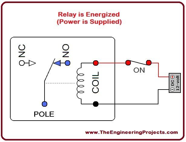
- From the above figure, you can see contact has been changed to normally open contact.
6. Relay Functions
- Relay has the three basic functions to perform.
- All of these three functions are provided in the table given in the figure shown below.
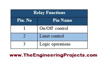
- Air conditioning control (to limit & control a very high power load) are the examples of on/off control of the relay.
- Limit control includes motor speed control (to disconnect it if it is moving with slow or faster than the desired speed).
- Test equipment is an example of logic operation, which connects the device with no. of test points.
7. Types of Relays
- This section will focus on the major types of relays commonly used these days.
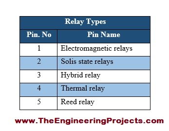
- There are several different types of relays.
- The basics types are listed in the table given in the figure shown below.
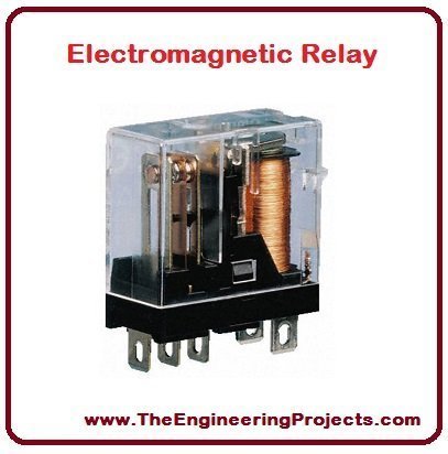
- Electromagnetic Relay is made up of magnetic, electrical and mechanical components. It has operating coil and mechanical contacts. When AC or DC supply is provided its mechanical contacts get either open of close. An electromagnetic relay is given in the figure shown below.
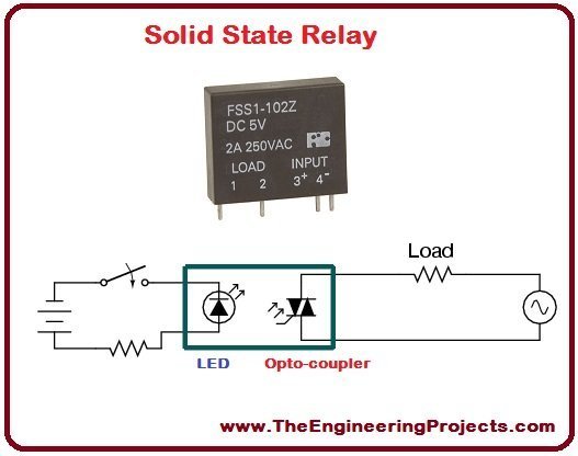
- Solid State Relay consists of solid state components. It is used to perform switching operation without any movement in its parts. Its power gain is higher than the electromagnetic relays because it requires low power as in input and provides high power at the output. Solid state is given in the figure shown below.
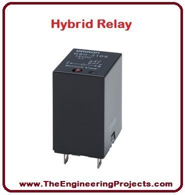
- Hybrid Relay is made up of electronic components and electromagnetic relays. Its input part consists of electronic circuitry which performs rectifications tasks. Its output part consist of electromagnetic relay. Hybrid relay is given in the figure shown below.
- Thermal Relay works on a very simple principle based on heat effect i.e. the rise in ambient temperature changes one position of the contact to another. Mostly it is used for the motor protection purposes. It consists of temperature sensors and control elements. Thermal relay is given n the figure shown below.

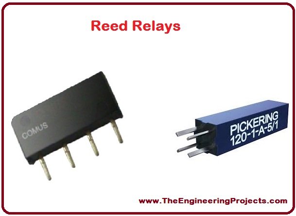
- Reed Relay has two magnetic strips. These strips are known as reed. These are sealed with a glass tube. The reed acts as blade as well as an armature. When magnetic field is applied to the coil. It wraps around the tube and reed start to move to perform the switching operation. Reed relays are given in the figure shown below.
8. Relay Applications
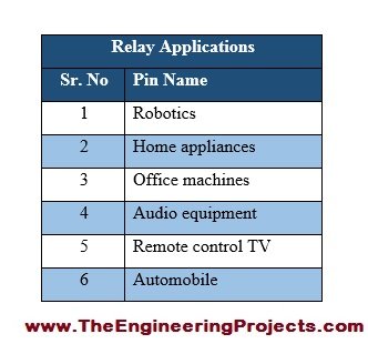
- Relay has a wide range of application in real life.
- Some of the major applications are listed in the table given in the figure shown below.
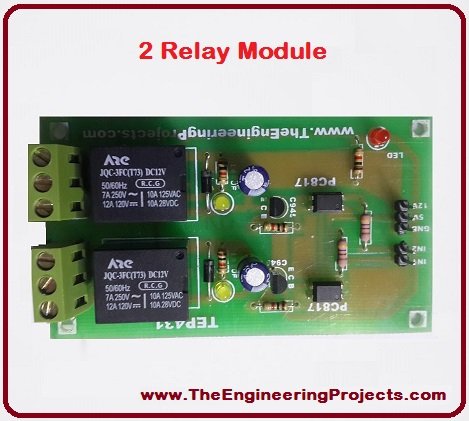
- Relay can also be used in relay boards for controlling either DC or stepper motor.
- One relay can control a single device, since two relay module has two relays so it can control two device simultaneously.
- Two relay board is given in the figure shown below.
- TV remote is another example of relay applications.
- TV remote is given in the figure shown below.
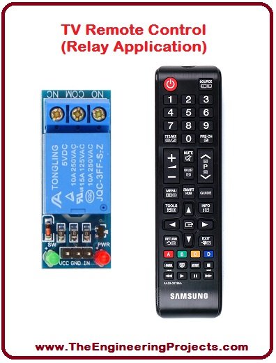
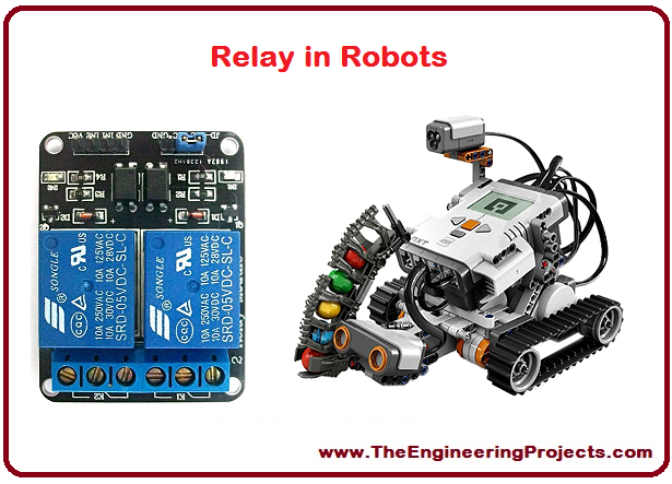
- Relay can also be used in mobile robots to control their motion properly.
- Visuals for the above step is given in the figure shown below.
9. Relay Simulation in Proteus
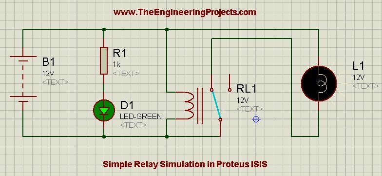
- I have made relay simulation in Proteus ISIS in order get a better idea about it.
- As the relay is energized, LED will be turned ON.
- A simple relay simulation in Proteus is given in the figure shown below.
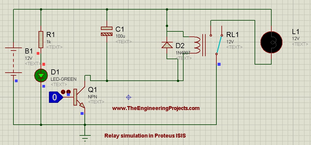
- I have also made another relay simulation in Proteus ISIS as shown in the figure below.
- When the relay gets energized, LED will be turned ON, as shown below.


@Haider Delay was because of EID as I have mentioned in the next port of this tutorial .... well it is posted now. Reply